Graphite anode: LiC₆, capacity, staging, SEI and lithium plating
Graphite is the dominant anode of lithium-ion batteries: on charging, lithium ions slide between its carbon layers until the fully lithiated compound LiC₆ is reached, which corresponds to a theoretical capacity of about 372 mAh g⁻¹ (Wu et al. 2026). It operates at about 0.1 V vs Li/Li⁺ (Clark et al. 2016), passing through a series of staging transitions on the way to LiC₆ (Chen et al. 2025). Its low potential gives cells a high voltage but also two characteristic problems: the electrolyte is reduced on its surface to form the solid electrolyte interphase (SEI), and at fast charging or low temperature lithium can plate as metal instead of intercalating (Chen et al. 2025).
Contents
Graphite anode at a glance
| Formula | C (graphite); fully lithiated LiC₆ (Wu et al. 2026) |
|---|---|
| Theoretical capacity | About 372 mAh g⁻¹ for LiC₆ (Wu et al. 2026; Chen et al. 2025); 371.9 mAh g⁻¹ per gram of carbon (calculated from one Li per six C) |
| Working potential | About 0.1 V vs Li⁺/Li (Clark et al. 2016) |
| Interlayer spacing | 0.335 nm in graphite, about 0.370 nm in LiC₆ (Wu et al. 2026); about 10% expansion along c (calculated from these values) |
| Lithiation mechanism | Intercalation between graphene layers through a series of stage transitions, ending in stage 1 (LiC₆) (Chen et al. 2025; Yamamoto et al. 2023) |
| Lithium entry | Through the edge planes; crossing the basal plane has a high energy barrier (Wu et al. 2026) |
| SEI formation | Electrolyte reduction near 0.7–0.8 V vs Li/Li⁺ on first charge (Chen et al. 2025; Wang et al. 2012); EC reduction is the first step of SEI growth (Gibson et al. 2021) |
| Lithium plating | When the graphite potential reaches 0 V vs Li/Li⁺ or below, favoured by fast charging and low temperature (Chen et al. 2025) |
| Low-temperature limit | Intercalation drops sharply below −20 °C; at −40 °C graphite reached 0 V after 106 mAh g⁻¹ (Chen et al. 2025) |
| Share of a cell | 12–21 wt% of a lithium-ion battery (Niu et al. 2022) |
| Sources | Natural, synthetic or recycled graphite (Kadivar et al. 2025) |
Graphite anode structure diagram
Graphite anode crystal structure (high-resolution SVG)
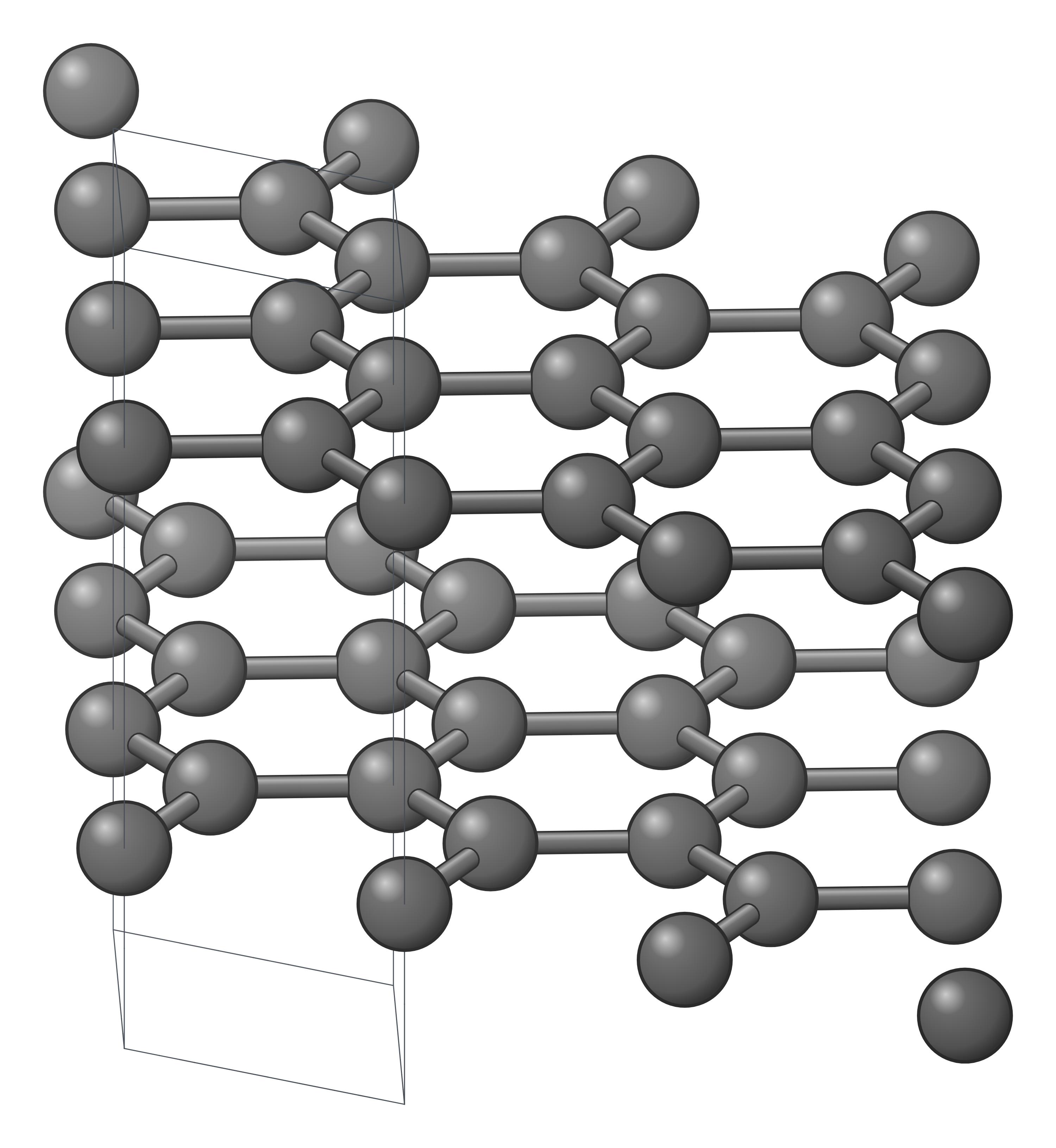
Graphite anode structure drawing (high-resolution SVG)
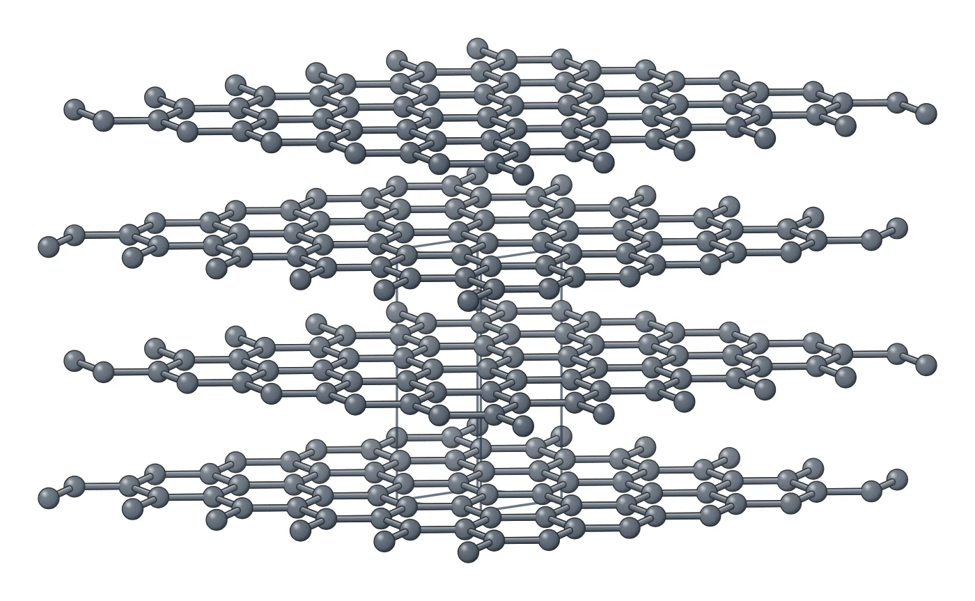
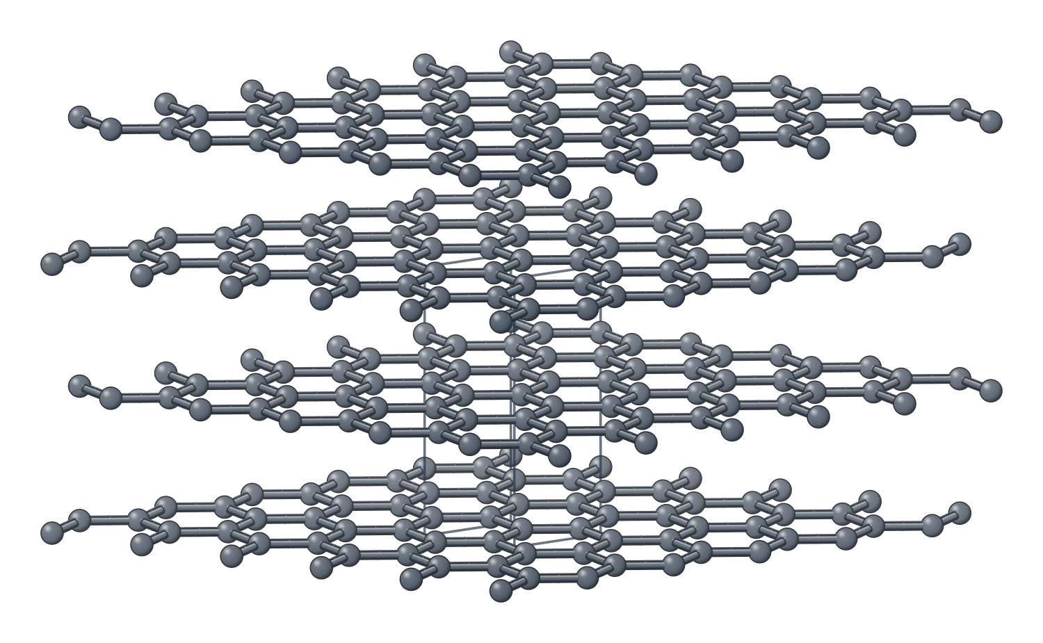
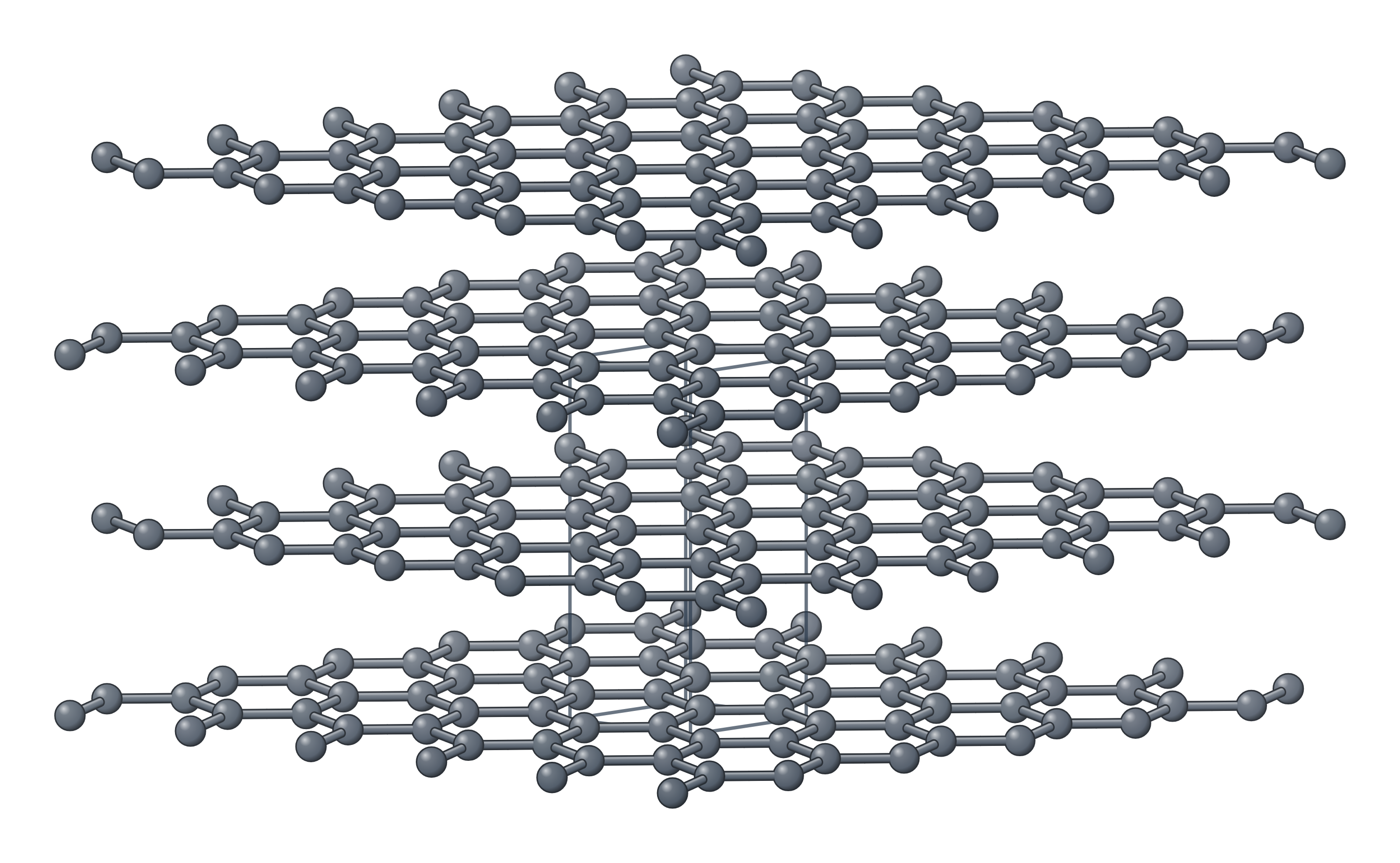
Graphite anode in 3D (interactive)
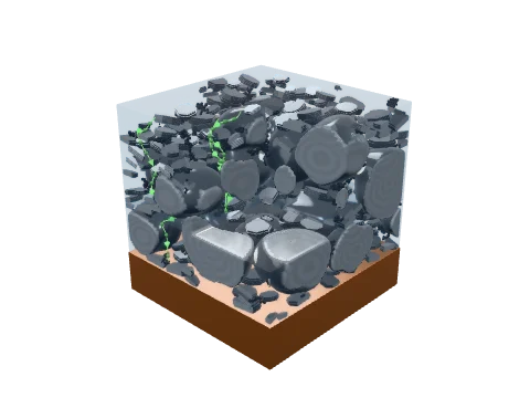
Loading the 3D model…
How lithium is stored in graphite
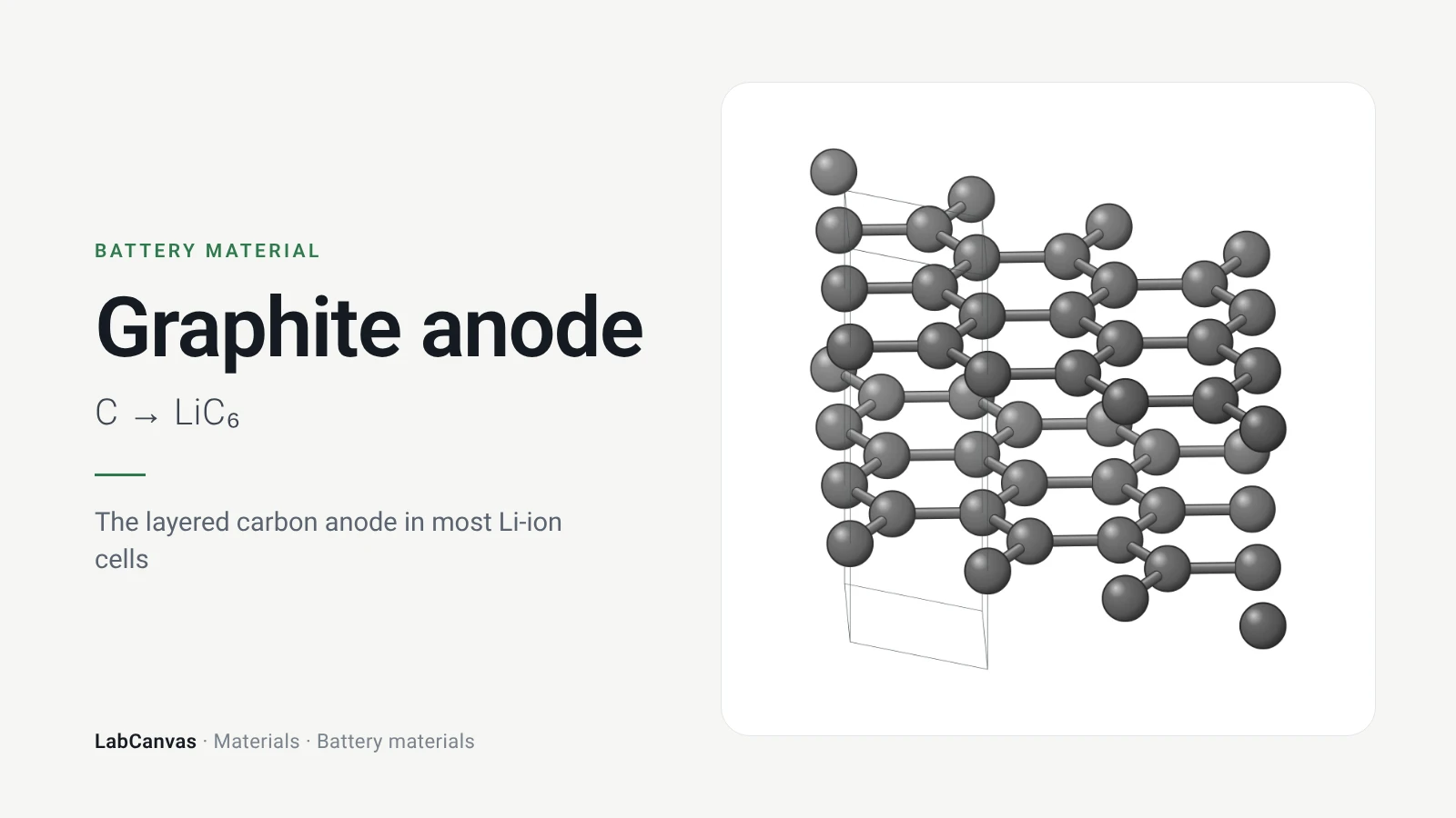
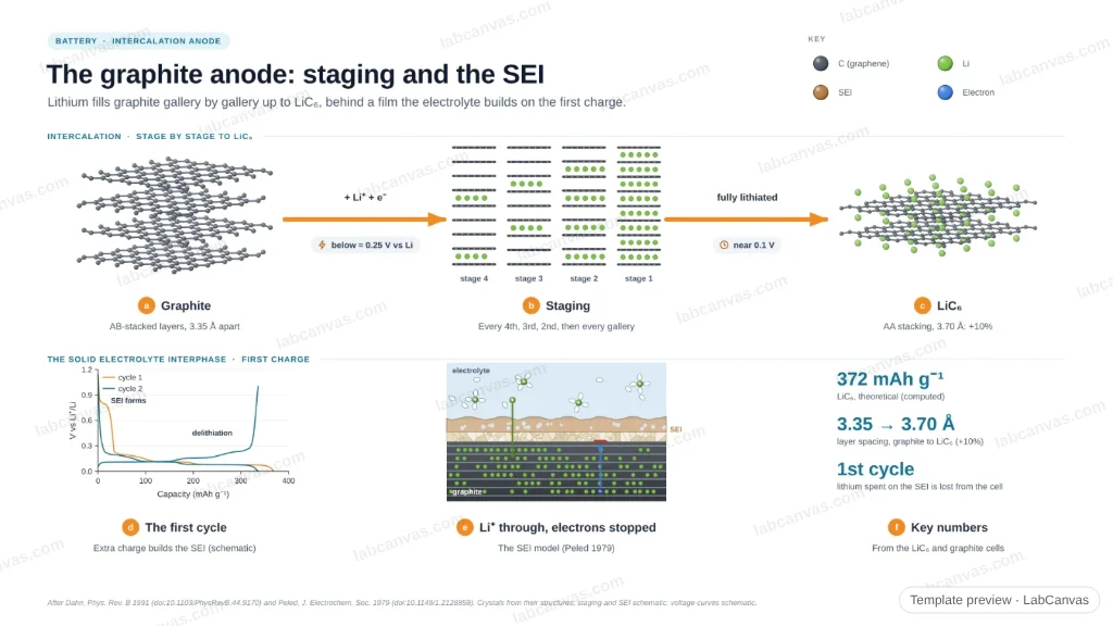
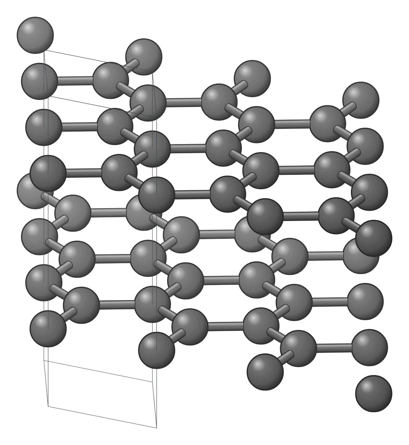
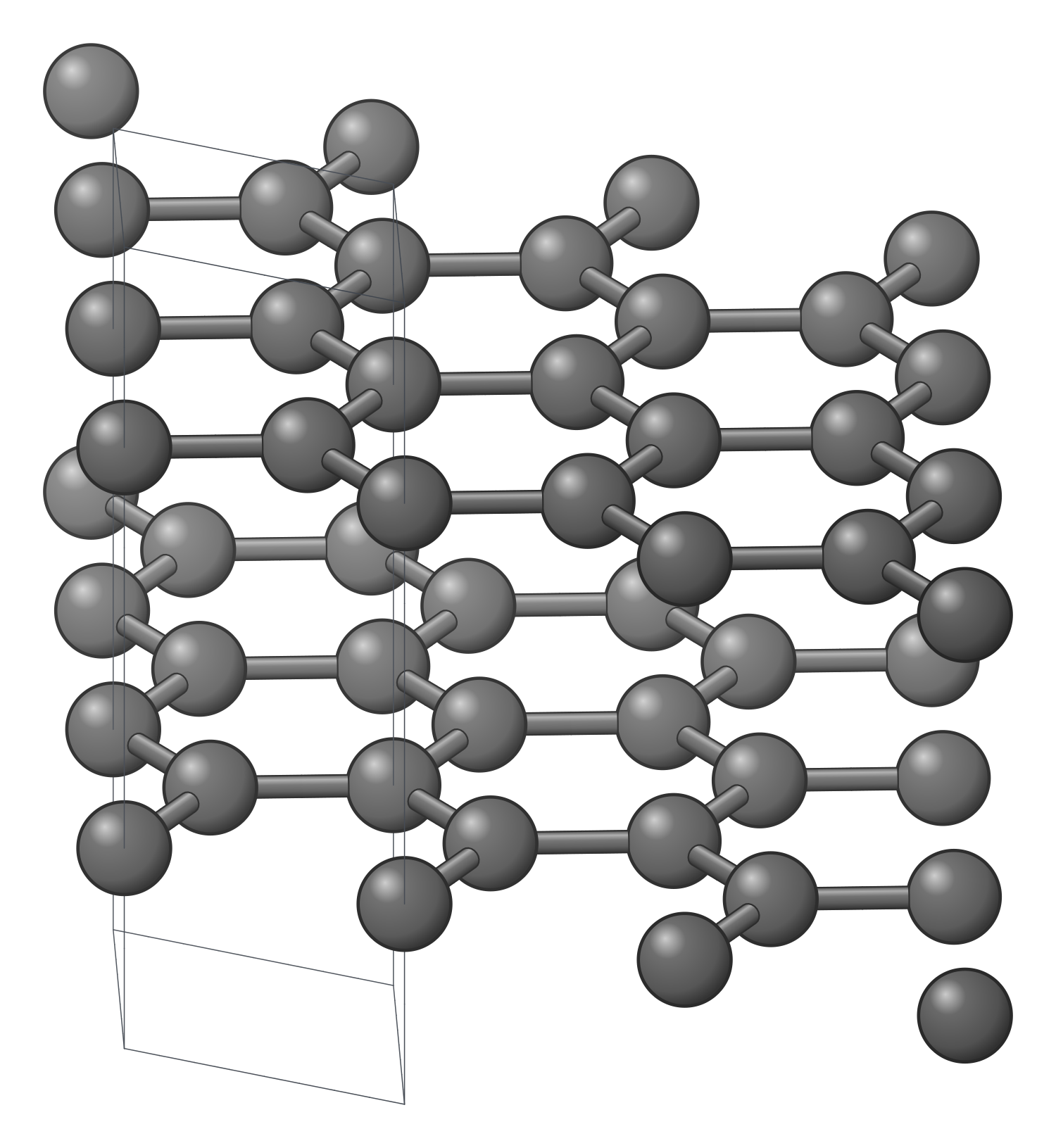
Graphite is a stack of graphene layers 0.335 nm apart. During charging, Li⁺ ions are intercalated between the layers; fully lithiated graphite is LiC₆, one lithium for every six carbon atoms, giving a theoretical capacity of about 372 mAh g⁻¹ (Wu et al. 2026), or 371.9 mAh g⁻¹ per gram of carbon (calculated). In LiC₆ the interlayer spacing opens to about 0.370 nm (Wu et al. 2026), roughly a 10% expansion along the stacking axis (calculated from these values).
Lithium enters graphite mainly through the edge planes of the particles: passing straight through the carbon hexagons of the basal plane has a high energy barrier (Wu et al. 2026). The layered structure therefore makes lithium transport strongly anisotropic, and large particles, few edge sites or unfavourable particle orientation lengthen the diffusion path (Wu et al. 2026).
Staging: the steps from graphite to LiC₆
Lithium does not fill graphite layer by layer at random. It forms stages, ordered structures in which lithium-filled galleries are separated by a fixed number of empty ones, and the stage structure changes by stepwise increases or decreases in the number of graphene layers between adjacent lithium-filled interlayers (Yamamoto et al. 2023). Each transition appears as a peak in the differential capacity (dQ/dV) of a graphite electrode: four peaks for the staging transitions, ending in stage 1, LiC₆, at the full theoretical capacity of 372 mAh g⁻¹ (Chen et al. 2025).
All of this happens at a low potential, about 0.1 V vs Li⁺/Li (Clark et al. 2016). That is what gives graphite-based cells their high voltage, and it is also why graphite sits so close to the potential at which lithium metal is deposited.
The SEI: why ethylene carbonate matters
At graphite’s low potential the organic electrolyte is not stable. On the first charge, before lithium intercalates, the electrolyte is reduced on the graphite surface: a shoulder near 0.7 V in the charging curve marks electrolyte reduction forming a primitive SEI-like layer (Chen et al. 2025), and on highly oriented pyrolytic graphite in LiPF₆ in ethylene carbonate/dimethyl carbonate, clusters grow on the step edges and terraces between 0.8 and 0.7 V vs Li⁺/Li from the reduction of solvent molecules (Wang et al. 2012). The reduction of ethylene carbonate (EC) is the initial stage of SEI growth (Gibson et al. 2021).
The resulting solid electrolyte interphase lets Li⁺ through (Wu et al. 2026) but protects the electrolyte from runaway reduction (Xia et al. 2017). EC remains irreplaceable as an electrolyte solvent for its balance of ionic conductivity and interfacial stability (Zhang et al. 2022). An EC-based electrolyte forms a protective SEI on graphite, whereas replacing EC entirely with fluoroethylene carbonate did not (Xia et al. 2017). Propylene carbonate, EC’s close relative, co-intercalates into graphite and exfoliates it (Xiang et al. 2015). EC has a cost: its high melting point of 36.4 °C limits low-temperature performance (Zhang et al. 2022).
Lithium plating at fast charge and low temperature
Lithium plating occurs when the graphite electrode potential reaches 0 V vs Li/Li⁺ and below. Fast charging and low temperature polarize the graphite, partly because intercalation is slow, and drive its potential towards and below 0 V, so Li⁺ is reduced to lithium metal on the surface instead of entering the layers (Chen et al. 2025). Plated lithium reacts with the electrolyte to form more SEI, can grow dendrites that short-circuit the cell and lead to thermal runaway, becomes electrochemically inactive “dead lithium” and blocks intercalation sites (Chen et al. 2025).
Cold makes it much worse. Between 30 °C and −20 °C graphite still showed well-defined staging plateaus and near-theoretical capacity, but at −30 °C and −40 °C its potential crossed 0 V after only 160 and 106 mAh g⁻¹, compared with 412 mAh g⁻¹ at −20 °C (Chen et al. 2025). For fast charging, graphite is redesigned to shorten diffusion paths and add lithium entry points, through smaller particles, pores, expanded interlayers and more edge sites, at the cost of more surface area, more SEI and lower initial Coulombic efficiency (Wu et al. 2026).
Natural vs synthetic graphite
Battery-grade graphite is made from three sources: natural graphite, synthetic graphite and, increasingly, graphite recycled from spent batteries. In a life cycle assessment, recycled graphite reduced the global warming potential of production by about 70% compared with the synthetic and natural routes (Kadivar et al. 2025). Graphite makes up 12–21 wt% of a lithium-ion battery (Niu et al. 2022). Spherical graphite is valued in commercial anodes for its processability and packing, which help electrode compaction density and uniformity (Wu et al. 2026).
Graphite is the anode in our overview of battery materials; in full cells it is paired with cathodes such as LiFePO₄ and layered NCM oxides (Wu et al. 2026).
How to draw the graphite anode structure
For a paper, slide or poster, draw graphite side on as parallel graphene layers 0.335 nm apart, with Li⁺ entering at the particle edges, and show LiC₆ with lithium in every gallery and the spacing opened to about 0.370 nm; staging can be shown by filling every second, third or fourth gallery. Add a thin SEI layer on the surface and, for fast charging, metallic lithium deposits on top of it. The LabCanvas figure editor Library has a battery crystal object for graphite that you can drop into a figure, recolour and resize, and the LabCanvas 3D Studio has a graphite anode model that you can turn and export as a high-resolution image.
Graphite compared with other anodes
| Anode | Storage mechanism | Potential vs Li⁺/Li | Capacity | Main issue |
|---|---|---|---|---|
| Graphite | Intercalation, staging to LiC₆ | ≈0.1 V | 372 mAh g⁻¹ (theoretical) | Lithium plating at fast charge and low temperature |
| Li₄Ti₅O₁₂ (titanate) | Intercalation | ≈1.6 V | — | Avoids lithium plating at the expense of cell voltage |
| Silicon | Alloying | Low | High theoretical capacity | Large volume change, unstable SEI |
Related materials
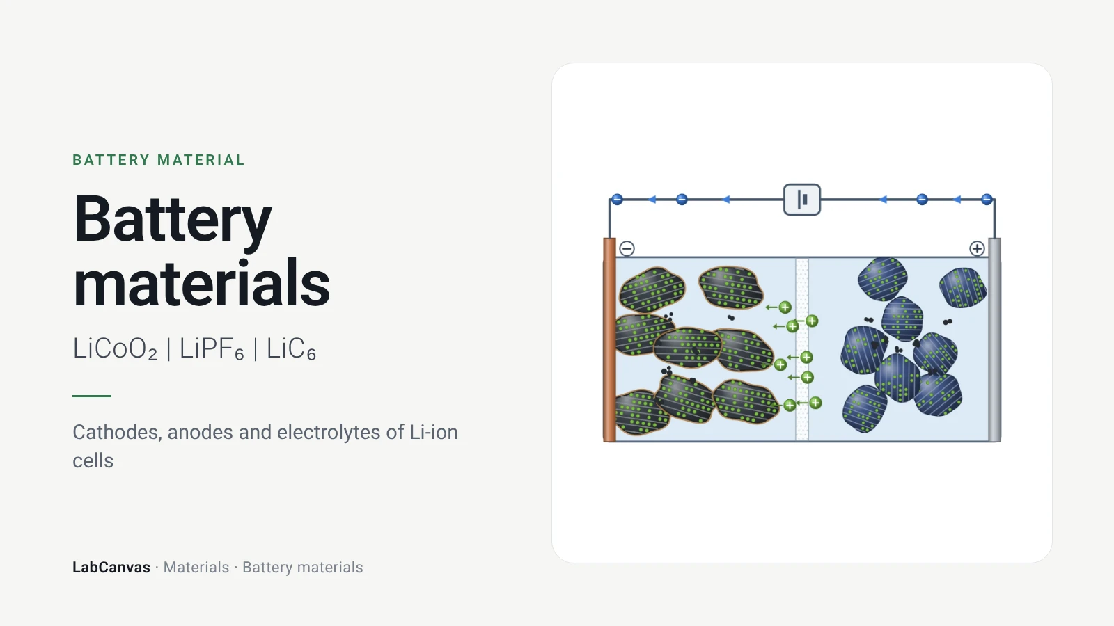
Battery materials
How a lithium-ion cell works and what is inside it: layered, spinel and olivine cathodes, graphite, silicon and lithium anodes, liquid and solid electrolytes.
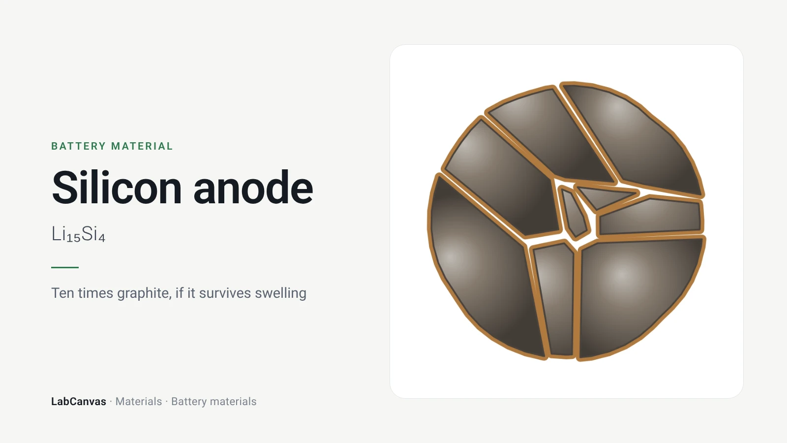
Silicon anode
Silicon anodes for Li-ion batteries: 3,579 mAh/g as Li₁₅Si₄, ~300% volume expansion, cracking and SEI, nanowires, yolk–shell, SiOx, Si–graphite, binders.
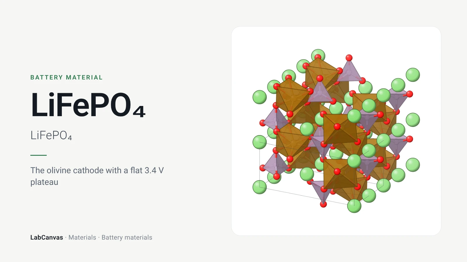
LiFePO₄ (LFP)
LiFePO₄ (LFP) cathode: olivine structure (Pnma), 1D lithium channels, the flat 3.4 V two-phase plateau, 170 mAh/g, carbon coating and why LFP is safe.
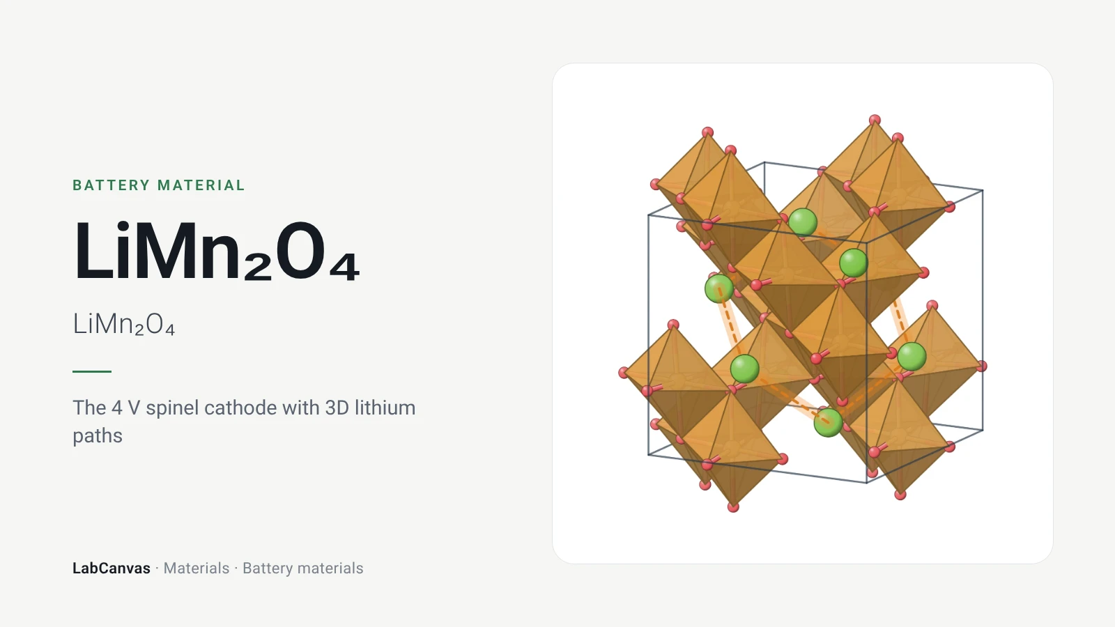
LiMn₂O₄ (spinel)
LiMn₂O₄ (LMO) spinel cathode: cubic Fd-3m structure, 3D lithium diffusion, 4.1 V plateaus, 148 mAh/g, Mn dissolution, Jahn–Teller fade and LiNi₀.₅Mn₁.₅O₄.
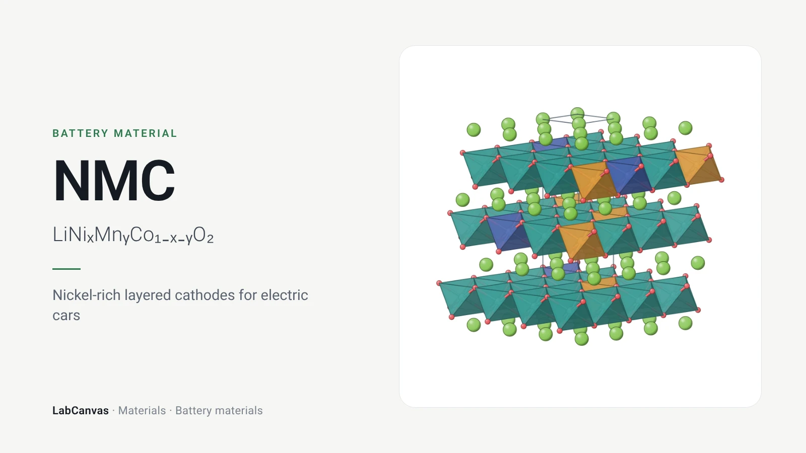
NMC (LiNiₓMnᵧCo₁₋ₓ₋ᵧO₂)
NMC cathodes (LiNiₓMnᵧCo₁₋ₓ₋ᵧO₂): layered structure, NMC111 to 811, why more nickel means more capacity but less stability, and the fixes.
More on LabCanvas
- The graphite anode: staging and the SEI: Editable figure template
- More battery figure templates: Ready-made, cited figures to edit
- Crystal structure figure software compared: VESTA, Mercury, CrystalMaker, Avogadro and LabCanvas
- Supercapacitor calculator: Free tool: capacitance, energy and power from cycling data
- Faradaic efficiency calculator: Free tool
- Battery figure templates: Cited, editable battery figures
- XRD Scherrer crystallite size calculator: Free tool
- Molar mass calculator: Free tool
- Journal figure size guide: Column widths and resolutions for 38 journals
- 3D models gallery: Turn MOFs, COFs, perovskites and more in 3D
Frequently asked questions
What is the theoretical capacity of a graphite anode?
About 372 mAh g⁻¹, corresponding to fully lithiated LiC₆, one lithium per six carbon atoms (Wu et al. 2026; Chen et al. 2025).
What is LiC₆?
The fully lithiated graphite intercalation compound formed at the end of charging, with lithium in every gallery between the graphene layers; it corresponds to stage 1 and a capacity of 372 mAh g⁻¹ (Chen et al. 2025; Wu et al. 2026).
At what voltage does lithium intercalate into graphite?
Graphite operates at about 0.1 V vs Li⁺/Li (Clark et al. 2016), close to the lithium deposition potential, which is why it can plate lithium.
What is staging in graphite?
The ordered way lithium fills graphite: stage structures in which lithium-filled galleries are separated by empty ones, changing stepwise as more lithium enters (Yamamoto et al. 2023). The transitions show up as four peaks in dQ/dV, ending in stage 1, LiC₆ (Chen et al. 2025).
What is the SEI on a graphite anode?
The solid electrolyte interphase, a passivating film formed when the electrolyte is reduced on graphite during the first charge, near 0.7–0.8 V vs Li/Li⁺ (Chen et al. 2025; Wang et al. 2012). Reduction of ethylene carbonate is the first step of its growth (Gibson et al. 2021).
Why is ethylene carbonate used with graphite?
Because EC forms a protective SEI on graphite (Xia et al. 2017), while propylene carbonate co-intercalates and exfoliates graphite (Xiang et al. 2015). Its drawback is a high melting point of 36.4 °C, which limits low-temperature performance (Zhang et al. 2022).
What causes lithium plating on graphite?
Plating happens when the graphite potential reaches 0 V vs Li/Li⁺ or below. Fast charging and low temperature polarize the electrode, because intercalation is slow, and push it there (Chen et al. 2025).
Why can’t you fast charge a lithium-ion battery in the cold?
Below about −20 °C lithium intercalation into graphite drops sharply: at −40 °C the electrode reached 0 V after only 106 mAh g⁻¹, so further charge plates lithium metal, which forms dead lithium and dendrites (Chen et al. 2025).
References
- H. Wu et al.. Intrinsic structural design of graphite anodes for fast-charging lithium-ion batteries: strategies, trade-offs, and perspectives. Front. Chem. 2026, 14, 1869263. doi:10.3389/fchem.2026.1869263
- B. Chen, N. Hope-Glenn, A. Wright, R. J. Messinger, A. Couzis. Mechanistic understanding of lithium-ion adsorption, intercalation, and plating during charging of graphite electrodes. ACS Electrochem. 2025, 1, 574–587. doi:10.1021/acselectrochem.4c00079
- S. J. Clark, D. Wang, A. R. Armstrong, P. G. Bruce. Li(V₀.₅Ti₀.₅)S₂ as a 1 V lithium intercalation electrode. Nat. Commun. 2016, 7, 10898. doi:10.1038/ncomms10898
- S. Yamamoto et al.. Electrochemical Li⁺ insertion/extraction reactions at LiPON/epitaxial graphene interfaces. ACS Nano 2023, 17, 16448–16460. doi:10.1021/acsnano.3c00158
- L. Wang, X. Deng, P.-X. Dai, Y.-G. Guo, D. Wang, L.-J. Wan. Initial solid electrolyte interphase formation process of graphite anode in LiPF₆ electrolyte: an in situ ECSTM investigation. Phys. Chem. Chem. Phys. 2012, 14, 7330–7336. doi:10.1039/c2cp40595d
- L. D. Gibson, J. Pfaendtner, C. J. Mundy. Probing the thermodynamics and kinetics of ethylene carbonate reduction at the electrode–electrolyte interface with molecular simulations. J. Chem. Phys. 2021, 155, 204703. doi:10.1063/5.0067687
- L. Xia, S. Lee, Y. Jiang, Y. Xia, G. Z. Chen, Z. Liu. Fluorinated electrolytes for Li-ion batteries: the lithium difluoro(oxalato)borate additive for stabilizing the solid electrolyte interphase. ACS Omega 2017, 2, 8741–8750. doi:10.1021/acsomega.7b01196
- H. Xiang et al.. The role of cesium cation in controlling interphasial chemistry on graphite anode in propylene carbonate-rich electrolytes. ACS Appl. Mater. Interfaces 2015, 7, 20687–20695. doi:10.1021/acsami.5b05552
- Z. Zhang, T. Yao, E. Wang, B. Sun, K. Sun, Z. Peng. Unlocking the low-temperature potential of propylene carbonate to −30 °C via N-methylpyrrolidone. ACS Appl. Mater. Interfaces 2022, 14, 45484–45493. doi:10.1021/acsami.2c13667
- B. Niu, J. Xiao, Z. Xu. Advances and challenges in anode graphite recycling from spent lithium-ion batteries. J. Hazard. Mater. 2022, 439, 129678. doi:10.1016/j.jhazmat.2022.129678
- S. Kadivar, S. Sharifian, E. Vahidi. Natural, synthetic, or recycled? A life cycle and techno-economic analysis of battery-grade graphite production. J. Environ. Manage. 2025, 395, 127747. doi:10.1016/j.jenvman.2025.127747
- S. Li, J. Xie, Z. Li, Z. Wang, X. Wang. Silicon-based anode materials for high-capacity lithium-ion batteries: recent advances and challenges. RSC Adv. 2026, 16, 47726–47759. doi:10.1039/d6ra05647d
Draw Graphite anode for your paper or slides
LabCanvas is a browser workspace for scientific figures: framework clusters, linkers and nets, crystal structures in 2D and 3D, graphs and posters, all editable.
Edit the Graphite anode figure