Silicon anode: capacity, volume expansion and how it is tamed
Silicon stores lithium by alloying, not intercalation: fully lithiated to Li₁₅Si₄ (3.75 Li per Si) it holds 3,579 mAh g⁻¹, more than nine times graphite, and 4,200 mAh g⁻¹ is quoted for Li₂₂Si₅ (Nepal & Dhakal 2026; Kawaura et al. 2023; Chamidah et al. 2023). The price is a volume change of about 300% that cracks particles and keeps breaking the solid electrolyte interphase (SEI) (Liu et al. 2014). Nanowires (Chan et al. 2008), sub-150 nm particles, yolk–shell carbon cages, SiOₓ and silicon–graphite blends are the main ways the swelling is managed.
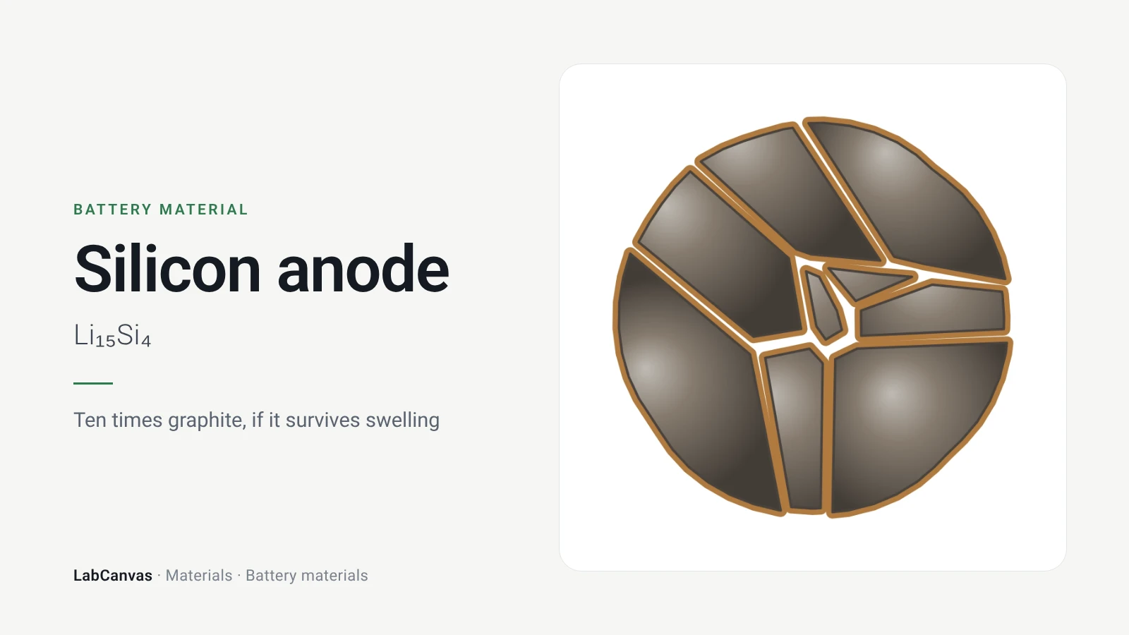
Contents
Silicon anode at a glance
| Formula | Si, lithiated to Li₁₅Si₄ in cells (Kawaura et al. 2023; Woodard et al. 2021) |
|---|---|
| Storage mechanism | Alloying with lithium; crystalline Si turns amorphous on first lithiation (Liu X. H. et al. 2012) |
| Theoretical capacity, Li₁₅Si₄ | 3,579 mAh g⁻¹ (Kawaura et al. 2023; Nepal & Dhakal 2026) |
| Theoretical capacity, Li₂₂Si₅ | 4,200 mAh g⁻¹ (Chamidah et al. 2023; Chan et al. 2008) |
| Versus graphite | More than nine times graphite (Nepal & Dhakal 2026); graphite: 372 mAh g⁻¹ (Lee et al. 2024) |
| Lithiation potential | ~0.4 V vs Li/Li⁺, against <0.2 V for graphite (Nepal & Dhakal 2026) |
| Volume change | About 300% at full lithiation (Liu et al. 2014; Nepal & Dhakal 2026); 400% quoted by Chan et al. 2008 |
| Critical particle size | ~150 nm: crystalline Si nanoparticles below it did not crack on first lithiation (Liu X. H. et al. 2012) |
| Nanowire anode | Reached the theoretical capacity and kept close to 75% of it on discharge (Chan et al. 2008) |
| Yolk–shell | ~2,800 mAh g⁻¹ at C/10; 74% after 1,000 cycles; Coulombic efficiency 99.84% (Liu N. et al. 2012) |
| Pomegranate | 97% capacity retention after 1,000 cycles; 99.87% Coulombic efficiency (Liu et al. 2014) |
| SiOₓ | About 1,600 mAh g⁻¹ for SiO, with lower expansion than Si but a low first-cycle efficiency (Wu & Wang 2026) |
| Key report | Chan et al., Nat. Nanotechnol. 3, 31 (2008): silicon nanowire anodes |
Silicon anode structure diagram
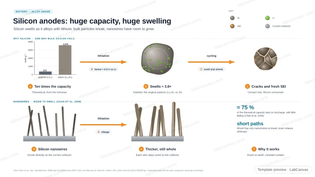
Silicon anode structure drawing (high-resolution SVG)



Why silicon? Capacity from alloying
Graphite stores one lithium per six carbons and tops out at 372 mAh g⁻¹ (Lee et al. 2024). Silicon instead forms lithium–silicon alloys. In a battery cell, deep lithiation ends in crystalline Li₁₅Si₄, 3.75 Li per Si, worth 3,579 mAh g⁻¹ (Kawaura et al. 2023; Nepal & Dhakal 2026; Woodard et al. 2021). The more lithium-rich Li₂₂Si₅ corresponds to 4,200 mAh g⁻¹, the figure often quoted as silicon's theoretical capacity (Chamidah et al. 2023; Chan et al. 2008). Either way silicon holds about ten times more charge per gram than graphite.
Silicon also lithiates at about 0.4 V vs Li/Li⁺, above graphite's <0.2 V, which lowers the risk of lithium plating but costs some full-cell voltage (Nepal & Dhakal 2026).
The problem: ~300% volume expansion
Taking up 3.75 lithium per atom swells silicon by about 300% (Liu et al. 2014; Nepal & Dhakal 2026). Repeated swelling and shrinking causes:
- Pulverisation. Particles crack and lose electrical contact, so capacity fades (Chan et al. 2008). In situ TEM showed that crystalline nanoparticles larger than about 150 nm crack on their first lithiation, because a moving boundary between the Si core and the amorphous Li–Si shell puts the surface under tension (Liu X. H. et al. 2012).
- An unstable SEI. Each expansion cracks the solid electrolyte interphase and exposes fresh silicon to the electrolyte, so the SEI keeps growing and consuming lithium. Together with pulverisation this limited silicon anodes to hundreds of cycles (Wu et al. 2012), and low initial and long-term Coulombic efficiency is still the main barrier to commercial use (Nepal & Dhakal 2026).
- Electrode-level damage. Binder fatigue, swelling of the electrode and loss of particle-to-particle and particle-to-current-collector contact (Nepal & Dhakal 2026).
How the swelling is managed
- Nanowires. Silicon nanowires accommodate the strain without pulverising, keep electronic contact and shorten lithium diffusion distances; they reached the theoretical capacity (Chan et al. 2008).
- Nanoparticles. Below a critical diameter of about 150 nm crystalline particles survive lithiation without fracture (Liu X. H. et al. 2012).
- Void space: yolk–shell and pomegranate. Sealing Si nanoparticles in thin carbon shells with built-in void lets the silicon expand without breaking the shell, so the SEI forms on a stable outer surface (Liu N. et al. 2012). Clustering these yolk–shells into micrometre "pomegranates" also cuts the electrolyte contact area and raises the volumetric capacity to 1,270 mAh cm⁻³ (Liu et al. 2014).
- Clamped shells. Double-walled silicon nanotubes with an outer silicon oxide shell expand only inwards, away from the electrolyte, and cycled over 6,000 times with more than 85% of their capacity (Wu et al. 2012).
- SiOₓ. Silicon suboxide reacts irreversibly on the first lithiation to lithium oxide and silicates that buffer the free silicon; SiO gives about 1,600 mAh g⁻¹ with much lower expansion than silicon, at the cost of a low first-cycle Coulombic efficiency (Wu & Wang 2026).
- Silicon–graphite blends. Adding silicon to graphite is the main industrial route today, though graphite-rich blends limit the gain in energy density (Nepal & Dhakal 2026).
- Binders. The binder must hold an electrode that swells: mixing Si nanopowder with alginate, a polysaccharide from brown algae, gave a stable anode with eight times the reversible capacity of graphite (Kovalenko et al. 2011).
Silicon among battery anodes
Silicon sits between graphite and lithium metal: lithium metal has the highest capacity (3,860 mAh g⁻¹) but faces safety and cycling problems, and silicon offers the next-highest (Nepal & Dhakal 2026). Lithium metal is the anode that solid electrolytes are meant to enable, while sodium-ion cells use hard carbon. For an overview of cathodes and anodes, see the battery materials hub.
How to draw a silicon anode
For a paper, slide or poster, show one silicon particle before and after lithiation with its volume roughly quadrupled (about 300% expansion), cracks running in from the surface for particles above ~150 nm, and a thickening SEI shell; then show the fix next to it, such as a nanowire on a current collector or a yolk–shell particle with void space inside a carbon shell. In LabCanvas, the figure editor's Library has battery objects, including silicon particle cracking, that you can drop in, recolour and label, and the 3D Studio has battery models for a cell-level view; export the figure as a high-resolution image.
Silicon compared with other lithium-ion anodes
| Anode | How it stores Li | Capacity | Volume change | Main problem | Source |
|---|---|---|---|---|---|
| Graphite | Intercalation | 372 mAh g⁻¹ | Small | Low capacity | Lee et al. 2024 |
| Silicon | Alloying to Li₁₅Si₄ | 3,579 mAh g⁻¹ | ~300% | Pulverisation, unstable SEI | Nepal & Dhakal 2026 |
| SiOₓ (SiO) | Conversion then alloying | ~1,600 mAh g⁻¹ | Lower than Si | Low first-cycle efficiency | Wu & Wang 2026 |
| Lithium metal | Plating | 3,860 mAh g⁻¹ | Electrode grows and shrinks | Dendrites, safety | Nepal & Dhakal 2026; Lee et al. 2024 |
Related materials
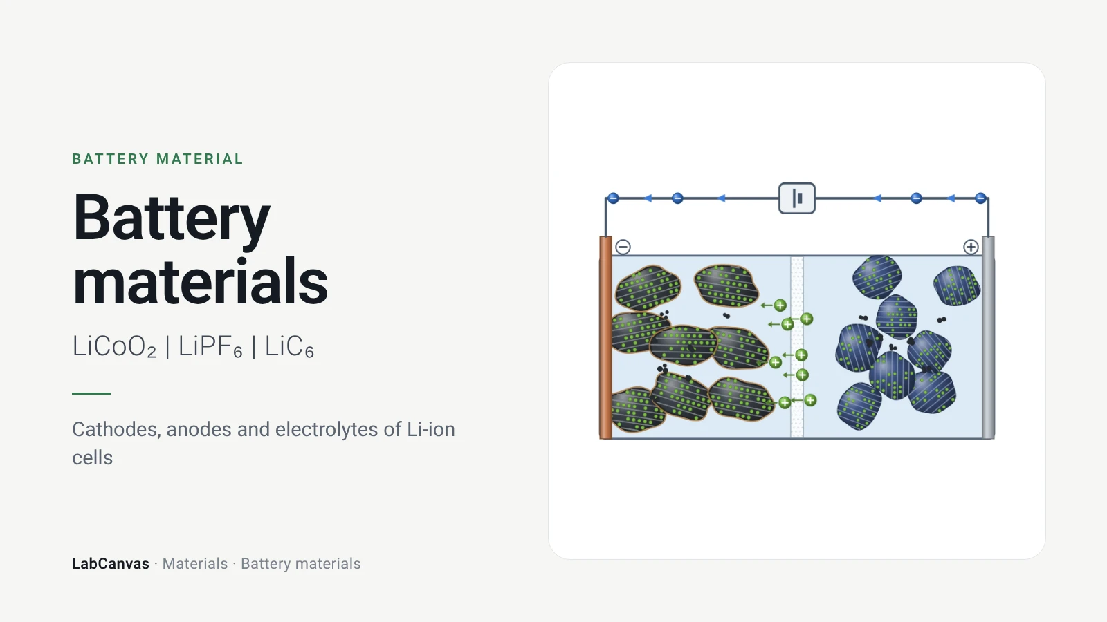
Battery materials
How a lithium-ion cell works and what is inside it: layered, spinel and olivine cathodes, graphite, silicon and lithium anodes, liquid and solid electrolytes.
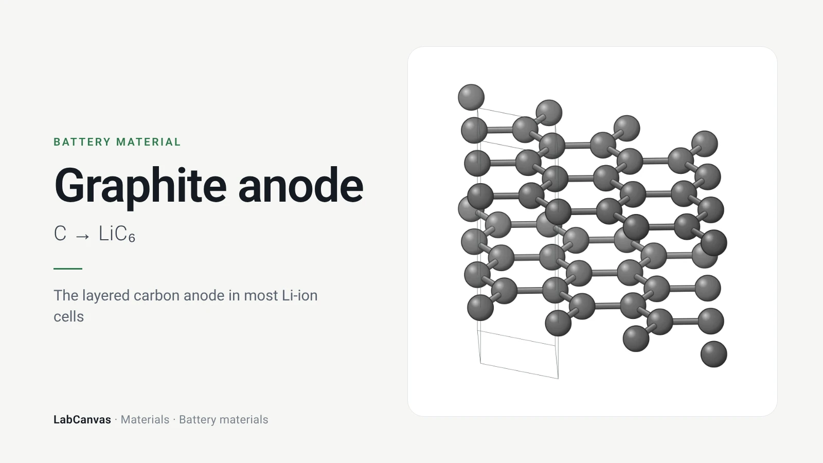
Graphite anode
Graphite anode in lithium-ion batteries: LiC₆ and 372 mAh/g, staging, intercalation near 0.1 V, the SEI from ethylene carbonate and lithium plating.
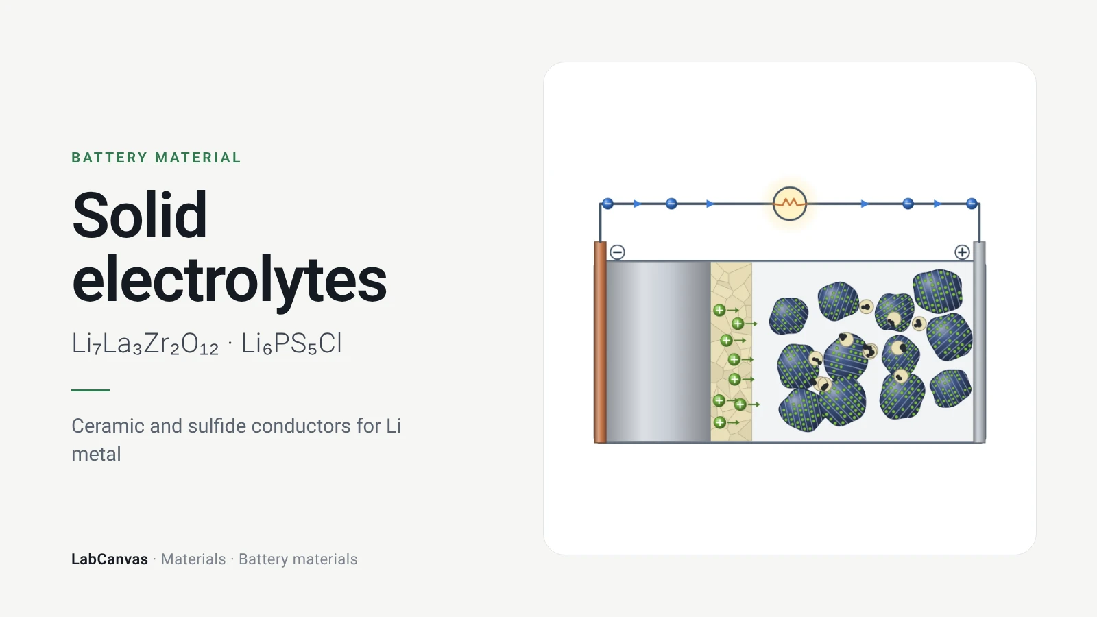
Solid electrolytes (LLZO, argyrodite)
Solid electrolytes for solid-state batteries: garnet LLZO (cubic vs tetragonal, Al/Ga/Ta doping), argyrodite Li₆PS₅Cl, LGPS, PEO, dendrites and Li metal.
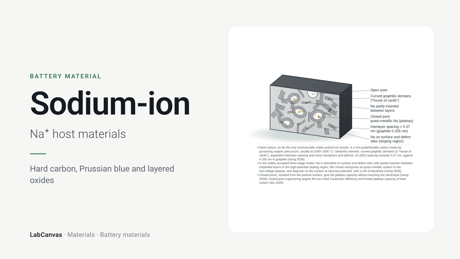
Sodium-ion battery materials
Sodium-ion battery materials: why sodium, hard carbon anodes (graphite stores little Na), Prussian blue, layered oxide and polyanion cathodes compared.
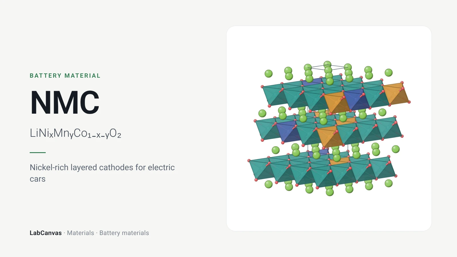
NMC (LiNiₓMnᵧCo₁₋ₓ₋ᵧO₂)
NMC cathodes (LiNiₓMnᵧCo₁₋ₓ₋ᵧO₂): layered structure, NMC111 to 811, why more nickel means more capacity but less stability, and the fixes.
More on LabCanvas
- Silicon anodes: huge capacity, huge swelling: Editable figure template
- More battery figure templates: Ready-made, cited figures to edit
- Crystal structure figure software compared: VESTA, Mercury, CrystalMaker, Avogadro and LabCanvas
- Supercapacitor calculator: Free tool: capacitance, energy and power from cycling data
- Faradaic efficiency calculator: Free tool
- Battery figure templates: Cited, editable battery figures
- XRD Scherrer crystallite size calculator: Free tool
- Molar mass calculator: Free tool
- Journal figure size guide: Column widths and resolutions for 38 journals
- 3D models gallery: Turn MOFs, COFs, perovskites and more in 3D
Frequently asked questions
What is the theoretical capacity of a silicon anode?
3,579 mAh g⁻¹ for Li₁₅Si₄, the phase that forms in room-temperature cells (Kawaura et al. 2023; Nepal & Dhakal 2026). The often-quoted 4,200 mAh g⁻¹ corresponds to Li₂₂Si₅ (Chamidah et al. 2023).
Why is the capacity of silicon 3579 or 4200 mAh/g?
The two numbers count different alloys: 3.75 Li per Si in Li₁₅Si₄ gives 3,579 mAh g⁻¹, and 4.4 Li per Si in Li₂₂Si₅ gives 4,200 mAh g⁻¹ (calculated from the formulas with Faraday’s constant; both values in Kawaura et al. 2023 and Chamidah et al. 2023).
How much does silicon expand in a lithium-ion battery?
About 300% at full lithiation (Liu et al., Nat. Nanotechnol. 2014; Nepal & Dhakal 2026), so a lithiated particle takes up roughly four times its original volume. Chan et al. 2008 quoted 400%.
Why do silicon anodes fail?
The repeated volume change cracks particles (pulverisation), breaks electrical contacts and keeps cracking the SEI, so the SEI grows and consumes lithium and electrolyte every cycle (Chan et al. 2008; Wu et al. 2012; Nepal & Dhakal 2026).
Why use silicon nanowires as an anode?
Nanowires accommodate the strain without pulverising, keep good electronic contact along their length and give short lithium diffusion distances; the first nanowire anodes reached silicon’s theoretical capacity (Chan et al., Nat. Nanotechnol. 2008).
What is a yolk–shell silicon anode?
Silicon nanoparticles sealed inside thin carbon shells with empty space between particle and shell. The silicon can swell into the void without breaking the shell, so the SEI on the shell stays stable: ~2,800 mAh g⁻¹ and 74% retention after 1,000 cycles (Liu et al., Nano Lett. 2012).
What is SiOx in batteries?
Silicon suboxide, a silicon-based anode that converts on its first lithiation into silicon embedded in lithium oxide and silicates. SiO gives about 1,600 mAh g⁻¹ and swells much less than silicon but loses lithium in the first cycle (Wu & Wang 2026).
Are silicon anodes used in commercial batteries?
Yes, mostly as silicon added to graphite: graphite–silicon composite anodes are the main industrial route today, while silicon-dominant anodes are still limited by Coulombic efficiency and cycle life (Nepal & Dhakal 2026).
References
- C. K. Chan, H. Peng, G. Liu, K. McIlwrath, X. F. Zhang, R. A. Huggins, Y. Cui. High-performance lithium battery anodes using silicon nanowires. Nat. Nanotechnol. 2008, 3, 31–35. doi:10.1038/nnano.2007.411
- N. Liu, H. Wu, M. T. McDowell, Y. Yao, C. Wang, Y. Cui. A yolk-shell design for stabilized and scalable Li-ion battery alloy anodes. Nano Lett. 2012, 12, 3315–3321. doi:10.1021/nl3014814
- N. Liu, Z. Lu, J. Zhao, M. T. McDowell, H.-W. Lee, W. Zhao, Y. Cui. A pomegranate-inspired nanoscale design for large-volume-change lithium battery anodes. Nat. Nanotechnol. 2014, 9, 187–192. doi:10.1038/nnano.2014.6
- H. Wu et al.. Stable cycling of double-walled silicon nanotube battery anodes through solid-electrolyte interphase control. Nat. Nanotechnol. 2012, 7, 310–315. doi:10.1038/nnano.2012.35
- X. H. Liu, L. Zhong, S. Huang, S. X. Mao, T. Zhu, J. Y. Huang. Size-dependent fracture of silicon nanoparticles during lithiation. ACS Nano 2012, 6, 1522–1531. doi:10.1021/nn204476h
- I. Kovalenko et al.. A major constituent of brown algae for use in high-capacity Li-ion batteries. Science 2011, 334, 75–79. doi:10.1126/science.1209150
- H. Kawaura, R. Suzuki, Y. Kondo, Y. Mahara. Scalable synthesis of porous silicon by acid etching of atomized Al–Si alloy powder for lithium-ion batteries. ACS Appl. Mater. Interfaces 2023, 15, 34909–34921. doi:10.1021/acsami.3c05521
- N. Chamidah et al.. Kinetic analysis of silicon–lithium alloying reaction in silicon single crystal using soft X-ray absorption spectroscopy. RSC Adv. 2023, 13, 17114–17120. doi:10.1039/d3ra02554c
- J. C. Woodard, W. P. Kalisvaart, S. Y. Sayed, B. C. Olsen, J. M. Buriak. Beyond thin films: clarifying the impact of c-Li₁₅Si₄ formation in thin film, nanoparticle, and porous Si electrodes. ACS Appl. Mater. Interfaces 2021, 13, 38147–38160. doi:10.1021/acsami.1c04293
- M. Nepal, T. P. Dhakal. Silicon anodes for next-generation Li-ion batteries: design, metrics, and practical routes to 500 Wh kg⁻¹ and 1000 cycles. Small Sci. 2026, 6, e70347. doi:10.1002/smsc.70347
- Y. Wu, Z. Wang. Si-based lithium-ion battery anodes: material design and challenges. Materials 2026, 19, 2580. doi:10.3390/ma19122580
- H. Lee, T. Yoon, O. B. Chae. Strategies for enhancing the stability of lithium metal anodes in solid-state electrolytes. Micromachines 2024, 15, 453. doi:10.3390/mi15040453
Draw Silicon anode for your paper or slides
LabCanvas is a browser workspace for scientific figures: framework clusters, linkers and nets, crystal structures in 2D and 3D, graphs and posters, all editable.
Edit the Silicon anode figure