Graphical abstract template · Graphical abstracts · Graphical abstract
PEM fuel cells: membrane, ionomer and catalyst layer, from molecule to stack
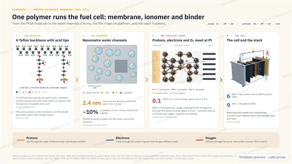
A zoom-out through a proton-exchange membrane fuel cell. The PFSA ionomer (Nafion) is a Teflon-like backbone with side chains ending in sulfonic acid; hydrated, it forms parallel water channels 1.8–3.5 nm wide through which protons move. The same ionomer coats platinum on carbon in the catalyst layer, where protons, electrons and oxygen must meet; cutting platinum to about 0.1 mg cm⁻² exposes an oxygen-transport resistance near the Pt. The cell and stack carry the power-density goals of 6 kW L⁻¹ by 2030 and 9 kW L⁻¹ by 2040.
Updated 6 cited papers87 editable layers
At a glance
- Category
- Graphical abstracts
- Method
- Graphical abstract
- Starting materials
- A PFSA ionomer, platinum on carbon, a gas-diffusion layer; hydrogen and air
- Product
- Electricity and water from a membrane electrode assembly in a stack
- Key result
- Channels 1.8–3.5 nm, mean 2.4 nm, crystallites ~(5 nm)², ~10 vol% (Schmidt-Rohr & Chen 2008); Pt 0.4–0.8 → ~0.1 mg cm⁻², losses above 1 A cm⁻² (Kongkanand & Mathias 2016); 6 and 9 kW L⁻¹ goals (Jiao et al. 2021)
- Figure
- 1920 × 1080 px (16:9), 87 editable layers, 3 generated objects
Step by step
- The ionomerA PTFE backbone with perfluoroether side chains ending in –SO₃H, which gives up its proton in water (Kusoglu & Weber 2017)
- The membraneHydrated, it forms parallel water channels 1.8–3.5 nm across (mean 2.4 nm at 20 vol% water), held by crystallites of about (5 nm)² (Schmidt-Rohr & Chen 2008)
- The catalyst layerThe ionomer is also the binder and proton path around Pt on carbon (Holdcroft 2014); at ~0.1 mg Pt cm⁻² oxygen reaching the Pt limits currents above 1 A cm⁻² (Kongkanand & Mathias 2016)
- The stackPower-density goals of 6 kW L⁻¹ by 2030 and 9 kW L⁻¹ by 2040 (Jiao et al. 2021)
Uses
- Graphical abstracts on fuel cells and ionomers
- Teaching how a PEM fuel cell membrane conducts protons
- Talks on low-platinum catalyst layers
Papers this template follows
- Schmidt-Rohr & Chen, “Parallel cylindrical water nanochannels in Nafion fuel-cell membranes”, Nat. Mater. 2008. doi:10.1038/nmat2074primary
- Kusoglu & Weber, “New insights into perfluorinated sulfonic-acid ionomers”, Chem. Rev. 2017. doi:10.1021/acs.chemrev.6b00159review
- Holdcroft, “Fuel cell catalyst layers: a polymer science perspective”, Chem. Mater. 2014. doi:10.1021/cm401445hreview
- Kongkanand & Mathias, “The priority and challenge of high-power performance of low-platinum proton-exchange membrane fuel cells”, J. Phys. Chem. Lett. 2016. doi:10.1021/acs.jpclett.6b00216review
- Jiao et al., “Designing the next generation of proton-exchange membrane fuel cells”, Nature 2021. doi:10.1038/s41586-021-03482-7review
- Debe, “Electrocatalyst approaches and challenges for automotive fuel cells”, Nature 2012. doi:10.1038/nature11115review
Drawn by LabCanvas after Schmidt-Rohr & Chen, Nat. Mater. 2008 (doi:10.1038/nmat2074); Kusoglu & Weber, Chem. Rev. 2017 (doi:10.1021/acs.chemrev.6b00159); Holdcroft, Chem. Mater. 2014 (doi:10.1021/cm401445h); Kongkanand & Mathias, J. Phys. Chem. Lett. 2016 (doi:10.1021/acs.jpclett.6b00216); Jiao et al., Nature 2021 (doi:10.1038/s41586-021-03482-7); Debe, Nature 2012 (doi:10.1038/nature11115). Catalyst layer and stack schematic; channel sizes to scale.
How templates are written and checked: editorial guidelines.
Questions
What does the “PEM fuel cells: membrane, ionomer and catalyst layer, from molecule to stack” template show?
A zoom-out through a proton-exchange membrane fuel cell. The PFSA ionomer (Nafion) is a Teflon-like backbone with side chains ending in sulfonic acid; hydrated, it forms parallel water channels 1.8–3.5 nm wide through which protons move. The same ionomer coats platinum on carbon in the catalyst layer, where protons, electrons and oxygen must meet; cutting platinum to about 0.1 mg cm⁻² exposes an oxygen-transport resistance near the Pt. The cell and stack carry the power-density goals of 6 kW L⁻¹ by 2030 and 9 kW L⁻¹ by 2040.
What are the steps shown in “PEM fuel cells: membrane, ionomer and catalyst layer, from molecule to stack”?
1. The ionomer: A PTFE backbone with perfluoroether side chains ending in –SO₃H, which gives up its proton in water (Kusoglu & Weber 2017). 2. The membrane: Hydrated, it forms parallel water channels 1.8–3.5 nm across (mean 2.4 nm at 20 vol% water), held by crystallites of about (5 nm)² (Schmidt-Rohr & Chen 2008). 3. The catalyst layer: The ionomer is also the binder and proton path around Pt on carbon (Holdcroft 2014); at ~0.1 mg Pt cm⁻² oxygen reaching the Pt limits currents above 1 A cm⁻² (Kongkanand & Mathias 2016). 4. The stack: Power-density goals of 6 kW L⁻¹ by 2030 and 9 kW L⁻¹ by 2040 (Jiao et al. 2021).
What are the starting materials and the product?
Starting materials: A PFSA ionomer, platinum on carbon, a gas-diffusion layer; hydrogen and air. Product: Electricity and water from a membrane electrode assembly in a stack.
Which papers is “PEM fuel cells: membrane, ionomer and catalyst layer, from molecule to stack” based on?
Schmidt-Rohr & Chen, “Parallel cylindrical water nanochannels in Nafion fuel-cell membranes”, Nat. Mater. 2008 (doi:10.1038/nmat2074); Kusoglu & Weber, “New insights into perfluorinated sulfonic-acid ionomers”, Chem. Rev. 2017 (doi:10.1021/acs.chemrev.6b00159); Holdcroft, “Fuel cell catalyst layers: a polymer science perspective”, Chem. Mater. 2014 (doi:10.1021/cm401445h); Kongkanand & Mathias, “The priority and challenge of high-power performance of low-platinum proton-exchange membrane fuel cells”, J. Phys. Chem. Lett. 2016 (doi:10.1021/acs.jpclett.6b00216); Jiao et al., “Designing the next generation of proton-exchange membrane fuel cells”, Nature 2021 (doi:10.1038/s41586-021-03482-7); Debe, “Electrocatalyst approaches and challenges for automotive fuel cells”, Nature 2012 (doi:10.1038/nature11115).
Can I edit the “PEM fuel cells: membrane, ionomer and catalyst layer, from molecule to stack” template?
Yes. Open it in the LabCanvas editor: all 87 layers are editable, including 3 generated objects (structures, plots, equipment) with their own settings. Change the text, colours and layout, then export PNG, TIFF or PDF at the width and DPI the journal asks for.
Do I need an account to use this template?
Not to view it here. To open and edit it, sign in to LabCanvas or create a free account (the free plan keeps up to 3 designs). Downloading the figure is part of LabCanvas Pro (US$19 a month or US$199 a year).