Quantikz: quantum circuit diagrams in LaTeX
Quick answer
\usetikzlibrary{quantikz2} after \usepackage{tikz} (or \usepackage{quantikz}, which in the current version 1.0.1 loads the same library) and write the circuit as a grid inside \begin{quantikz} … \end{quantikz}: every row is a qubit wire, & separates the time steps and \\ starts the next wire. The wires are drawn for you. Put one gate command in a cell: \gate{H} for a box, \ctrl{1} for a control dot whose line goes one row down to a \targ{} (together a CNOT), \meter{} for a measurement and \lstick{\ket{0}} for the label at the start of a wire. Gate labels are already in math mode; \lstick text is not.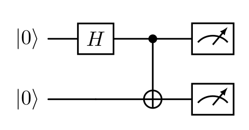
\usepackage{tikz} \usetikzlibrary{quantikz2}\begin{quantikz}
\lstick{\ket{0}} & \gate{H} & \ctrl{1} & \meter{} \\
\lstick{\ket{0}} & & \targ{} & \meter{}
\end{quantikz}Full document
\documentclass[border=4pt]{standalone}
\usepackage{tikz}
\usetikzlibrary{quantikz2}
\begin{document}
\begin{quantikz}
  \lstick{\ket{0}} & \gate{H} & \ctrl{1} & \meter{} \\
  \lstick{\ket{0}} &          & \targ{}  & \meter{}
\end{quantikz}
\end{document}Contents
Loading quantikz: quantikz2 and the legacy library
Quantikz, by Alastair Kay, is on CTAN and in TeX Live and MiKTeX. The current release, 1.0.1 of 2023-05-24, ships two TikZ libraries, and the README calls quantikz2 “the current release” and the old one “legacy”:
| Preamble line | What you get |
|---|---|
\usetikzlibrary{quantikz2} | Version 1.0.1, the form the tutorial recommends (after \usepackage{tikz}) |
\usepackage{quantikz} | The same: in 1.0.1, quantikz.sty is a three-line wrapper that loads TikZ and \usetikzlibrary{quantikz2} |
\usetikzlibrary{quantikz} | The legacy library, version 0.9.8, kept so that old documents still look as they did |
So the answer to “quantikz or quantikz2?” is quantikz2, and with an up-to-date TeX distribution \usepackage{quantikz} already gives it to you. The two differ mainly in the wires. In quantikz2 every cell gets a wire by default, so the \qw and \cw commands of the old syntax are unnecessary (old code that still contains \qw renders the same). The legacy library draws only the wire coming into a gate from the left, so every empty cell needs \qw, as the picture below shows. The tutorial’s conversion notes (§VII.A) list the other changes: labels of \meter are now in math mode, \ctrlbundle is replaced by plain \ctrl, styling goes through keys such as [style={…}], and quantikz2 is less forgiving when \targ and similar commands lack their {}.
Use the quantikz environment, not tikzcd (which also works, as quantikz is built on tikz-cd, but is kept only for compatibility). If you submit to arXiv or a journal whose TeX installation is older than 2023, copy tikzlibraryquantikz2.code.tex from your TeX tree into the folder with your source, as the tutorial advises. If you use quantikz in a paper, the author asks you to cite arXiv:1809.03842.
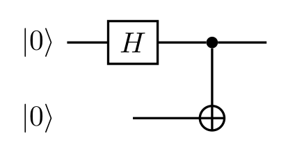
\usepackage{tikz} \usetikzlibrary{quantikz}\begin{quantikz}
% legacy library (0.9.8): a gate draws only the wire coming in from the left,
% so empty cells and the last cell need \qw
\lstick{\ket{0}} & \gate{H} & \ctrl{1} & \qw \\
% the same row without \qw: two wire segments are missing
\lstick{\ket{0}} & & \targ{} &
\end{quantikz}Full document
\documentclass[border=4pt]{standalone}
\usepackage{tikz}
\usetikzlibrary{quantikz}
\begin{document}
\begin{quantikz}
  % legacy library (0.9.8): a gate draws only the wire coming in from the left,
  % so empty cells and the last cell need \qw
  \lstick{\ket{0}} & \gate{H} & \ctrl{1} & \qw \\
  % the same row without \qw: two wire segments are missing
  \lstick{\ket{0}} &          & \targ{}  &
\end{quantikz}
\end{document}The grid: wires, cells and single-qubit gates
A circuit is a matrix: cells separated by &, rows by \\. A gate in a cell gets a wire coming in from the cell on its left and one going out to the cell on its right, so three rules avoid most surprises:
- Leave the first cell of a row for the label (
\lstick) or empty: a gate there has no incoming wire. - End a row with
&after the last gate, or no wire leaves it. - Put the gate command first in its cell; commands such as
\setwiretype,\qwbundle,\sliceor\gategroupcome after it.
The single-qubit commands, as listed in §III of the tutorial:
| Command | Draws |
|---|---|
\gate{H} | A box; the label is in math mode, so \gate{R_z(\theta)} works as written |
\phase{\alpha} | A filled dot on the wire with a label |
\push{T} | Text on the wire without a box |
\meter{}, \meter{\ket{\pm}} | The measurement symbol, optionally with the basis written above; \metercw is a variant |
\measuretab{x}, \measure{x}, \meterD{x}, \inputD{0} | Measurement and input shapes that end or start a wire |
\trash{}, \ground{} | Terminations for a traced-out wire |
Commands that look argument-free still need their braces: \meter{}, \targ{}, \control{}. A wire after a measurement stays quantum unless you change it (see classical wires below).
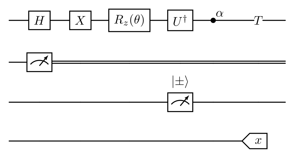
\usepackage{tikz} \usetikzlibrary{quantikz2}\begin{quantikz}[row sep=0.6cm]
% single-qubit gates: the label is already in math mode
& \gate{H} & \gate{X} & \gate{R_z(\theta)} & \gate{U^\dagger} & \phase{\alpha} & \push{T} & \\
% measurements
& \meter{} & \setwiretype{c} & & & & & \\
& & & & \meter{\ket{\pm}} & & & \\
& & & & & & \measuretab{x}
\end{quantikz}Full document
\documentclass[border=4pt]{standalone}
\usepackage{tikz}
\usetikzlibrary{quantikz2}
\begin{document}
\begin{quantikz}[row sep=0.6cm]
  % single-qubit gates: the label is already in math mode
  & \gate{H} & \gate{X} & \gate{R_z(\theta)} & \gate{U^\dagger} & \phase{\alpha} & \push{T} & \\
  % measurements
  & \meter{} & \setwiretype{c} &    &                   &                &          & \\
  &          &                 &    & \meter{\ket{\pm}} &                &          & \\
  &          &                 &    &                   &                & \measuretab{x}
\end{quantikz}
\end{document}Controlled gates: CNOT, CZ, Toffoli and SWAP
\ctrl{n} draws a control dot and a vertical line n rows down (negative n goes up). What sits at the other end decides the gate:
- CNOT:
\ctrl{1}on the control wire,\targ{}(⊕) in the same column one row down. - CZ:
\ctrl{1}and\control{}, a dot with no line of its own. - Open (negated) control:
\octrl{1}, or\ctrl[open]{1};\ocontrol{}is the open target dot. - Controlled-U:
\ctrl{1}above any\gate{U}; the target may also be above,\ctrl{-1}. - Toffoli: chain the lines,
\ctrl{1}on the first wire,\ctrl{1}on the second,\targ{}on the third. - SWAP:
\swap{1}and\targX{}(two crosses).\swap[partial swap={\pi/4}]{1}puts a label in a circle on the line.
For one control with several targets, run the line to the farthest target and put \targ{} on each wire it crosses; \wire[u]{q} adds an extra vertical quantum wire from a cell when you need one.
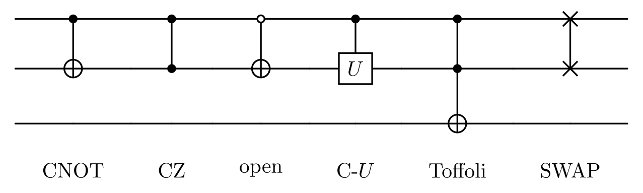
\usepackage{tikz} \usetikzlibrary{quantikz2}\begin{quantikz}[wire types={q,q,q,n}, column sep=0.45cm]
& \ctrl{1} & & \ctrl{1} & & \octrl{1} & & \ctrl{1} & & \ctrl{1} & & \swap{1} & \\
& \targ{} & & \control{} & & \targ{} & & \gate{U} & & \ctrl{1} & & \targX{} & \\
& & & & & & & & & \targ{} & & & \\
& \push{\text{CNOT}} & & \push{\text{CZ}} & & \push{\text{open}} & & \push{\text{C-}U} & & \push{\text{Toffoli}} & & \push{\text{SWAP}} &
\end{quantikz}Full document
\documentclass[border=4pt]{standalone}
\usepackage{tikz}
\usetikzlibrary{quantikz2}
\begin{document}
\begin{quantikz}[wire types={q,q,q,n}, column sep=0.45cm]
  & \ctrl{1}     & & \ctrl{1}   & & \octrl{1}       & & \ctrl{1}  & & \ctrl{1}            & & \swap{1}  & \\
  & \targ{}      & & \control{} & & \targ{}         & & \gate{U}  & & \ctrl{1}            & & \targX{}  & \\
  &              & &            & &                 & &           & & \targ{}             & &           & \\
  & \push{\text{CNOT}} & & \push{\text{CZ}} & & \push{\text{open}} & & \push{\text{C-}U} & & \push{\text{Toffoli}} & & \push{\text{SWAP}} &
\end{quantikz}
\end{document}Multi-qubit gates
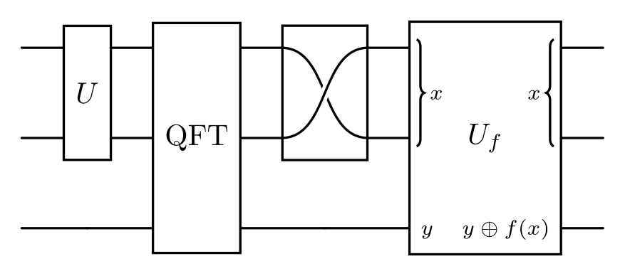
The first optional argument of \gate is the number of wires: \gate[2]{U} in the top row of the gate covers that wire and the one below. Leave the cells it covers empty. \meter spans wires the same way.
\gate[2,swap]{}draws a two-qubit box with crossing wires inside.\gateinput{$x$}and\gateoutput{$x$}write labels inside the left and right edge of a gate, on the current row;\gateinput[2]{…}groups two wires with a brace. These labels are in text mode, and the gate does not widen for them: give a minimum width as the second optional argument,\gate[3][1.8cm]{U_f}.\gate[3, disable auto height]{\verticaltext{MAJ}}stops a tall label from stretching every wire.
\usepackage{tikz} \usetikzlibrary{quantikz2}\begin{quantikz}
& \gate[2]{U} & \gate[3]{\mathrm{QFT}} & \gate[2,swap]{} & \gate[3][1.8cm]{U_f}\gateinput[2]{$x$}\gateoutput[2]{$x$} & \\
& & & & & \\
& & & & \gateinput{$y$}\gateoutput{$y\oplus f(x)$} &
\end{quantikz}Full document
\documentclass[border=4pt]{standalone}
\usepackage{tikz}
\usetikzlibrary{quantikz2}
\begin{document}
\begin{quantikz}
  & \gate[2]{U} & \gate[3]{\mathrm{QFT}} & \gate[2,swap]{} & \gate[3][1.8cm]{U_f}\gateinput[2]{$x$}\gateoutput[2]{$x$} & \\
  &             &                        &                 &                                                          & \\
  &             &                        &                 & \gateinput{$y$}\gateoutput{$y\oplus f(x)$}               &
\end{quantikz}
\end{document}Labelling wires: \lstick, \rstick and \midstick
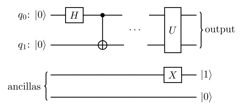
\lstick{…} labels the start of a wire and goes in the first cell; \rstick{…} labels the end and goes in the last cell; \midstick{…} interrupts the wires in the middle (useful for “⋯” or for an equals sign between two circuits). Their text is in text mode, so maths needs dollars: \lstick{$q_0$}. With a number they span several wires and draw a brace: \lstick[2]{ancillas}; brackets=none removes it and braces={…} styles it.
Quantikz defines \ket, \bra, \proj and \braket, which work without math mode. If another package (physics, braket) already defines them, quantikz keeps the other definition; load quantikz after it and put \forceredefine at the end of the preamble if you want quantikz’s versions.
\usepackage{tikz} \usetikzlibrary{quantikz2}\begin{quantikz}
\lstick{$q_0$: \ket{0}} & \gate{H} & \ctrl{1} & \midstick[2,brackets=none]{$\cdots$} & \gate[2]{U} & \rstick[2]{output} \\
\lstick{$q_1$: \ket{0}} & & \targ{} & & & \\
\lstick[2]{ancillas} & & & & \gate{X} & \rstick{\ket{1}} \\
& & & & & \rstick{\ket{0}}
\end{quantikz}Full document
\documentclass[border=4pt]{standalone}
\usepackage{tikz}
\usetikzlibrary{quantikz2}
\begin{document}
\begin{quantikz}
  \lstick{$q_0$: \ket{0}} & \gate{H} & \ctrl{1} & \midstick[2,brackets=none]{$\cdots$} & \gate[2]{U} & \rstick[2]{output} \\
  \lstick{$q_1$: \ket{0}} &          & \targ{}  &                                      &             & \\
  \lstick[2]{ancillas}    &          &          &                                      & \gate{X}    & \rstick{\ket{1}} \\
                          &          &          &                                      &             & \rstick{\ket{0}}
\end{quantikz}
\end{document}Classical wires, bundles and wire types
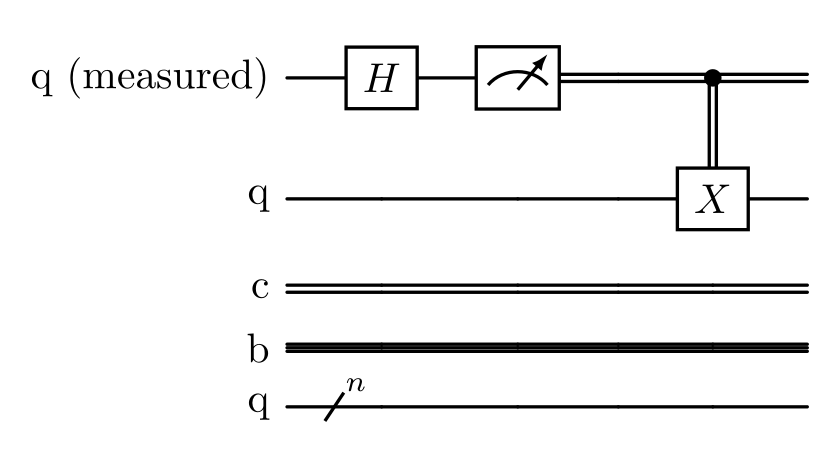
Wire types are q (quantum, the default), c (classical, a double line), b (bundle, three lines) and n (none). Set them for the whole circuit with \begin{quantikz}[wire types={q,q,c,b,q}], one letter per row, or change one wire from a cell onwards with \setwiretype{c}. The change applies to the wire that ends in that cell, the segment running back to the previous cell, which is why the \setwiretype{c} goes in the cell after the \meter{}.
- A classically controlled gate:
\ctrl[vertical wire=c]{1}on the classical wire above\gate{X}. \setwiretype{n}ends a wire;\wireoverride{n}blanks a single segment without changing the rest of the row.\qwbundle{n}puts a slash labelled n through a quantum wire, the usual notation for a register of n qubits.classical gap=0.05cmchanges the distance between the two lines of classical wires (default 0.03 cm).
\usepackage{tikz} \usetikzlibrary{quantikz2}\begin{quantikz}[wire types={q,q,c,b,q}]
\lstick{q (measured)} & \gate{H} & \meter{} & \setwiretype{c} & \ctrl[vertical wire=c]{1} & \\
\lstick{q} & & & & \gate{X} & \\
\lstick{c} & & & & & \\
\lstick{b} & & & & & \\
\lstick{q} & \qwbundle{n} & & & &
\end{quantikz}Full document
\documentclass[border=4pt]{standalone}
\usepackage{tikz}
\usetikzlibrary{quantikz2}
\begin{document}
\begin{quantikz}[wire types={q,q,c,b,q}]
  \lstick{q (measured)} & \gate{H} & \meter{} & \setwiretype{c} & \ctrl[vertical wire=c]{1} & \\
  \lstick{q}            &          &          &                 & \gate{X}                  & \\
  \lstick{c}            &          &          &                 &                           & \\
  \lstick{b}            &          &          &                 &                           & \\
  \lstick{q}            & \qwbundle{n} &      &                 &                           &
\end{quantikz}
\end{document}Slices (barriers) and gate groups
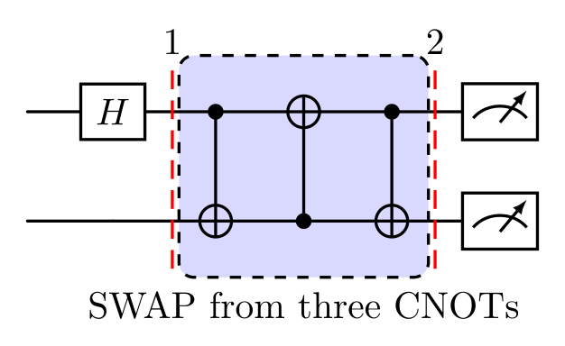
\slice{label} draws a dashed vertical line after the column it is written in, labelled at the top: the usual way to mark the steps of a circuit, and the quantikz equivalent of a Qiskit-style barrier (\slice{} for no label). \begin{quantikz}[slice all] slices every column and numbers the slices; remove end slices=1, slice titles=step \col, slice style=blue and slice label style={…} adjust them. Slicing every column needs every row to have the same number of cells.
\gategroup[2,steps=3]{label} draws a box whose top-left corner is the cell it is written in, covering 2 wires and 3 columns, with the label above. style={dashed, rounded corners, fill=blue!15} styles the box, background puts it behind the gates (needed with a fill), and label style={label position=below, anchor=north, yshift=-0.2cm} moves the label under it.
\usepackage{tikz} \usetikzlibrary{quantikz2}\begin{quantikz}
& \gate{H}\slice{1} & \ctrl{1}\gategroup[2,steps=3,style={dashed,rounded corners,fill=blue!15,inner xsep=2pt},background,label style={label position=below,anchor=north,yshift=-0.2cm}]{SWAP from three CNOTs} & \targ{} & \ctrl{1}\slice{2} & \meter{} \\
& & \targ{} & \ctrl{-1} & \targ{} & \meter{}
\end{quantikz}Full document
\documentclass[border=4pt]{standalone}
\usepackage{tikz}
\usetikzlibrary{quantikz2}
\begin{document}
\begin{quantikz}
  & \gate{H}\slice{1} & \ctrl{1}\gategroup[2,steps=3,style={dashed,rounded corners,fill=blue!15,inner xsep=2pt},background,label style={label position=below,anchor=north,yshift=-0.2cm}]{SWAP from three CNOTs} & \targ{} & \ctrl{1}\slice{2} & \meter{} \\
  &                   & \targ{}  & \ctrl{-1} & \targ{} & \meter{}
\end{quantikz}
\end{document}Example: quantum teleportation
The Bell state circuit at the top of this page (H, then CNOT) is the first half of teleportation. Here it prepares the shared pair on the lower two wires; the sender then entangles |ψ⟩ with her half (CNOT, H), measures both qubits, and the two classical results control X and Z corrections on the receiver’s qubit, which ends in |ψ⟩. The classical wires start with \setwiretype{c} after each \meter{}, the corrections use \ctrl[vertical wire=c], and \setwiretype{n} stops each classical wire after its control.
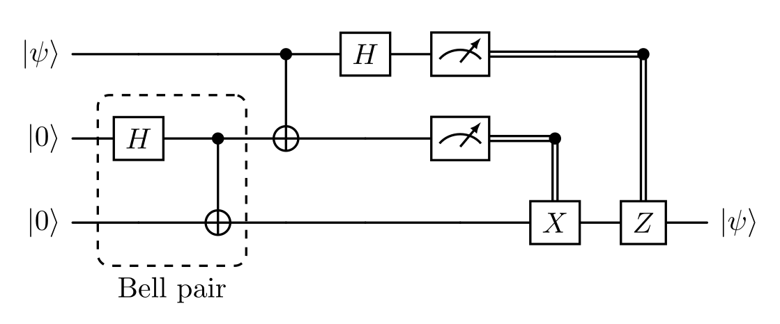
\usepackage{tikz} \usetikzlibrary{quantikz2}\begin{quantikz}
\lstick{\ket{\psi}} & & & \ctrl{1} & \gate{H} & \meter{} & \setwiretype{c} & \ctrl[vertical wire=c]{2} & \setwiretype{n} \\
\lstick{\ket{0}} & \gate{H}\gategroup[2,steps=2,style={dashed,rounded corners,inner xsep=2pt},label style={label position=below,anchor=north,yshift=-0.2cm}]{Bell pair} & \ctrl{1} & \targ{} & & \meter{} & \ctrl[vertical wire=c]{1}\setwiretype{c} & \setwiretype{n} & \\
\lstick{\ket{0}} & & \targ{} & & & & \gate{X} & \gate{Z} & \rstick{\ket{\psi}}
\end{quantikz}Full document
\documentclass[border=4pt]{standalone}
\usepackage{tikz}
\usetikzlibrary{quantikz2}
\begin{document}
\begin{quantikz}
  \lstick{\ket{\psi}} &          &          & \ctrl{1} & \gate{H} & \meter{} & \setwiretype{c} & \ctrl[vertical wire=c]{2} & \setwiretype{n} \\
  \lstick{\ket{0}}    & \gate{H}\gategroup[2,steps=2,style={dashed,rounded corners,inner xsep=2pt},label style={label position=below,anchor=north,yshift=-0.2cm}]{Bell pair} & \ctrl{1} & \targ{} & & \meter{} & \ctrl[vertical wire=c]{1}\setwiretype{c} & \setwiretype{n} & \\
  \lstick{\ket{0}}    &          & \targ{}  &          &          &          & \gate{X}        & \gate{Z}                  & \rstick{\ket{\psi}}
\end{quantikz}
\end{document}Example: three-qubit quantum Fourier transform
The QFT is a staircase of Hadamards and controlled phase rotations Rk, followed by a SWAP that reverses the qubit order. Each rotation is a \gate{R_k} on the target with \ctrl{-1} or \ctrl{-2} pointing up from the control.
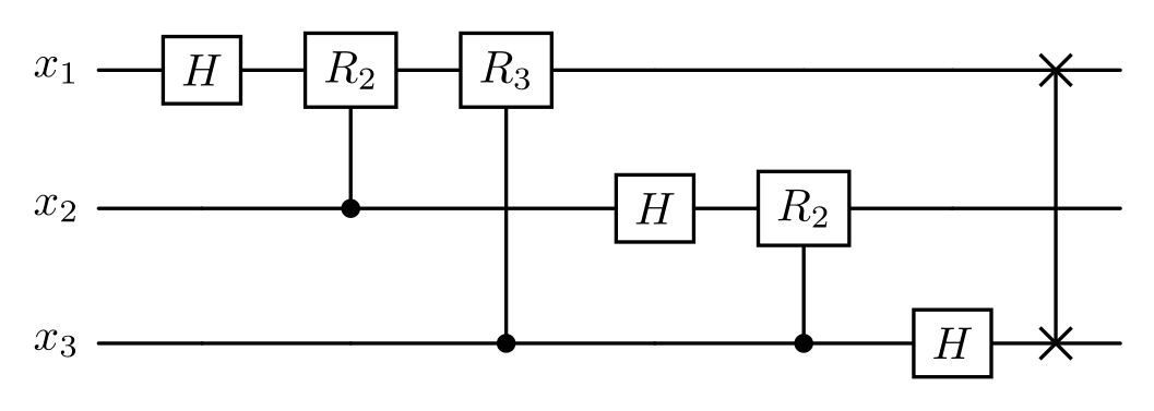
\usepackage{tikz} \usetikzlibrary{quantikz2}\begin{quantikz}
\lstick{$x_1$} & \gate{H} & \gate{R_2} & \gate{R_3} & & & & \swap{2} & \\
\lstick{$x_2$} & & \ctrl{-1} & & \gate{H} & \gate{R_2} & & & \\
\lstick{$x_3$} & & & \ctrl{-2} & & \ctrl{-1} & \gate{H} & \targX{} &
\end{quantikz}Full document
\documentclass[border=4pt]{standalone}
\usepackage{tikz}
\usetikzlibrary{quantikz2}
\begin{document}
\begin{quantikz}
  \lstick{$x_1$} & \gate{H} & \gate{R_2} & \gate{R_3} &          &            &          & \swap{2} & \\
  \lstick{$x_2$} &          & \ctrl{-1}  &            & \gate{H} & \gate{R_2} &          &          & \\
  \lstick{$x_3$} &          &            & \ctrl{-2}  &          & \ctrl{-1}  & \gate{H} & \targX{} &
\end{quantikz}
\end{document}Styling, spacing and scaling
- Whole circuit:
thin lines(closer to the old QCircuit look),transparent(no white fill in gates),color=blueandbackground color=…. - One gate:
\gate[style={fill=teal!20}, label style=cyan]{H},\meter[style={draw=blue}]{},\phase[style=green]{\beta}. - Every gate of a kind:
\tikzset{operator/.append style={fill=red!20}}; the style names areoperator(\gate),meter,slice,phase,circlewc(\targ),crossx2(\swap) and others (§V.A). - Spacing:
column sep=0.4cmandrow sep=0.6cmset the gaps between cells;row sep={0.9cm,between origins}spaces the wires evenly whatever the gate heights.&[2cm]widens one column gap and\\[1cm]one row gap. - Scaling: put the circuit in a node,
\begin{tikzpicture}\node[scale=0.8]{\begin{quantikz} … \end{quantikz}};\end{tikzpicture}, or use\begin{adjustbox}{width=\linewidth}from the adjustbox package to fit a width.
For a document with many circuits, TikZ externalization (\usetikzlibrary{external}, \tikzexternalize) works with quantikz and turns each circuit into a separate PDF; that is also the tutorial’s advice for publishers that do not accept TikZ code.
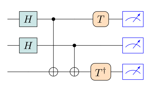
\usepackage{tikz} \usetikzlibrary{quantikz2}\begin{quantikz}[thin lines, row sep={0.9cm,between origins}, column sep=0.4cm]
& \gate[style={fill=teal!20}]{H} & \ctrl{2} & & \gate[style={fill=orange!25,rounded corners}]{T} & \meter[style={draw=blue}]{} \\
& \gate[style={fill=teal!20}]{H} & & \ctrl{1} & & \meter[style={draw=blue}]{} \\
& & \targ{} & \targ{} & \gate[style={fill=orange!25,rounded corners}]{T^\dagger} & \meter[style={draw=blue}]{}
\end{quantikz}Full document
\documentclass[border=4pt]{standalone}
\usepackage{tikz}
\usetikzlibrary{quantikz2}
\begin{document}
\begin{quantikz}[thin lines, row sep={0.9cm,between origins}, column sep=0.4cm]
  & \gate[style={fill=teal!20}]{H} & \ctrl{2} & & \gate[style={fill=orange!25,rounded corners}]{T} & \meter[style={draw=blue}]{} \\
  & \gate[style={fill=teal!20}]{H} &          & \ctrl{1} & & \meter[style={draw=blue}]{} \\
  &                                & \targ{}  & \targ{}  & \gate[style={fill=orange!25,rounded corners}]{T^\dagger} & \meter[style={draw=blue}]{}
\end{quantikz}
\end{document}Alternatives: qcircuit and yquant
- Qcircuit (2.6.0) is the older Xy-pic package that quantikz was modelled on, and the format Qiskit’s LaTeX circuit drawer writes. The notation converts almost one to one:
\multigate{n}becomes\gate[n+1],\targbecomes\targ{},\meterbecomes\meter{}(tutorial §VII). - yquant (0.9.1, 2026-07-19) describes a circuit as a list of operations on named registers instead of a grid and places the gates itself, which is convenient for long algorithms.
To edit quantikz code and see the result as you type, paste it into the LabCanvas TikZ editor, which compiles with TeX Live 2026, the same renderer as the pictures on this page.
Common errors and how to fix them
| LaTeX says (or you see) | Cause and fix |
|---|---|
| LaTeX Error: Environment quantikz undefined. | Add \usetikzlibrary{quantikz2} after \usepackage{tikz}, or \usepackage{quantikz}. |
| Missing $ inserted. (reported at \end{quantikz}, from \lstick{q_0}) | \lstick, \rstick, \midstick, \gateinput and \gateoutput are in text mode: write \lstick{$q_0$}. (\ket{0} works without dollars.) |
| Missing } inserted. (reported at \end{quantikz}, from \meter without braces) | Commands that take an optional argument and look argument-free still need an empty pair of braces: \meter{}, \targ{}, \control{}, \targX{}. |
| Undefined control sequence. \errmessage #1->\tikzcd@errmessage … I think the culprit is a tikzcd arrow in cell … | With \slice or \gategroup, the last row ended with \\ or is shorter than the others. Delete the final \\ and give the last row as many cells (&) as the longest row (tutorial §VIII). |
| \meter{$x$} or \gate{$H$} gives an upright x or H | Gate and meter labels are already in math mode, so the dollars switch back to text. Write \meter{x}, \gate{H}. |
| No wire after the last gate of a row | End the row with & after the gate, so there is a cell for the outgoing wire. |
| Wire segments missing, or a gate drawn as plain text in its cell | With the legacy \usetikzlibrary{quantikz}, empty cells need \qw; switch to quantikz2. With quantikz2, make the gate command the first thing in its cell and put \setwiretype, \qwbundle or \slice after it. |
| The classical (double) wire starts one cell late | \setwiretype{c} changes the segment that ends in its cell, the one coming from the left. Put it in the cell right after the \meter{}, or set wire types={…} for the whole row. |
Frequently asked questions
How do I draw a quantum circuit in LaTeX?
Load \usepackage{tikz} and \usetikzlibrary{quantikz2}, then write \begin{quantikz} \lstick{\ket{0}} & \gate{H} & \ctrl{1} & \meter{} \\ \lstick{\ket{0}} & & \targ{} & \meter{} \end{quantikz}. Rows are wires, & separates time steps, and wires are drawn automatically.
Should I use quantikz or quantikz2?
quantikz2. It is the current release (1.0.1); \usetikzlibrary{quantikz} loads the legacy 0.9.8 code, which needs \qw for every empty cell. \usepackage{quantikz} loads quantikz2 in version 1.0.1, so on a current TeX distribution it gives you the new version too.
How do I draw a CNOT gate in quantikz?
Put \ctrl{1} on the control wire and \targ{} in the same column of the wire below. For a target above the control use \ctrl{-1}; for CZ replace \targ{} by \control{}.
How do I draw a barrier or a dashed line between steps?
Use \slice{} (or \slice{label}) in a cell: it draws a dashed vertical line after that column across all wires. [slice all] on the environment slices every column; slice style={black, dotted} changes the look.
How do I draw a measurement followed by a classical wire?
Write \meter{} and put \setwiretype{c} in the next cell; the wire from the meter on becomes a double line. A gate controlled by the result is \ctrl[vertical wire=c]{n} above (or below) a \gate{…}.
How do I make a quantikz circuit fit the page?
Reduce column sep and row sep, or scale it: wrap it in \begin{adjustbox}{width=\linewidth} … \end{adjustbox} (adjustbox package) or in a scaled node, \node[scale=0.8]{\begin{quantikz}…\end{quantikz}}; inside a tikzpicture.
References
- quantikz package on CTAN (v1.0.1, 2023-05-24)ctan.org
- Tutorial on the Quantikz Package (PDF on CTAN)mirrors.ctan.org
- Quantikz tutorial, §II Basic usage: gates and measurementmirrors.ctan.org
- Quantikz tutorial, §II.B Controlled gates and §II.C Labelling circuitsmirrors.ctan.org
- Quantikz tutorial, §II.D Boxing/highlighting and §II.E Slicingmirrors.ctan.org
- Quantikz tutorial, §III Commands & optionsmirrors.ctan.org
- Quantikz tutorial, §IV Spacingmirrors.ctan.org
- Quantikz tutorial, §V Styling & customisingmirrors.ctan.org
- Quantikz tutorial, §VII.A Converting from Quantikz to Quantikz2 and §VIII Troubleshootingmirrors.ctan.org
- A. Kay, Tutorial on the Quantikz Package, arXiv:1809.03842arxiv.org
- tikz-cd package on CTAN (v1.0), which quantikz builds onctan.org
- PGF/TikZ manual, §20 Matrices and Alignmenttikz.dev
- qcircuit package on CTAN (v2.6.0)ctan.org
- yquant package on CTAN (v0.9.1, 2026-07-19)ctan.org
The facts on this page were checked against these sources, and every picture is the code with it typeset with TeX Live 2026. Code on this page: CC0 1.0, copy it freely.
Try the code in your browserEvery snippet on this page opens in the free TikZ editor: it is typeset with TeX Live as you type, with errors pointed at their line.
Open the TikZ editor