How to draw a rectangle in TikZ (with rounded corners and text)
Quick answer
\draw (0,0) rectangle (3,1.5);: the two coordinates are opposite corners. Add rounded corners to round all four corners with the default 4pt radius, or give a size such as rounded corners=8pt. For a rectangle with text inside, use a node: \node[draw, rounded corners, minimum width=3cm, minimum height=1.5cm] {Text inside}; sets a minimum size, grows to fit longer text, and can be named and joined with arrows.
\usepackage{tikz}\begin{tikzpicture}
\draw[rounded corners] (0,0) rectangle (3,1.5); % default radius 4pt
\draw[rounded corners=8pt, fill=blue!15] (3.5,0) rectangle (6.5,1.5);
\node[draw, rounded corners, minimum width=3cm, minimum height=1.5cm]
at (8.5,0.75) {Text inside};
\end{tikzpicture}Full document
\documentclass[border=4pt]{standalone}
\usepackage{tikz}
\begin{document}
\begin{tikzpicture}
  \draw[rounded corners] (0,0) rectangle (3,1.5);                % default radius 4pt
  \draw[rounded corners=8pt, fill=blue!15] (3.5,0) rectangle (6.5,1.5);
  \node[draw, rounded corners, minimum width=3cm, minimum height=1.5cm]
    at (8.5,0.75) {Text inside};
\end{tikzpicture}
\end{document}Contents
Draw a rectangle from two corners
The rectangle path operation takes the current point as one corner and the coordinate after it as the opposite corner, which then becomes the new current point. So \draw (0,0) rectangle (3,2); is a 3 × 2 rectangle, and the corners can be given in any order: (3,2) rectangle (0,0) draws the same shape.
When you know the width and height rather than the far corner, write the second corner relative to the first with ++: (4.5,0) rectangle ++(2,1) is 2 wide and 1 high. Coordinates without a unit are in centimetres (the default x and y vectors are 1 cm).
The command decides what happens to the outline: \draw strokes it, \fill fills it, \filldraw does both, and \path does neither (useful for an invisible rectangle that only enlarges the picture). Because a rectangle is a closed path, it can always be filled, and it never gets arrow tips.
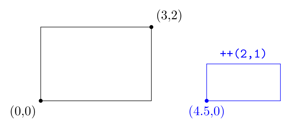
\usepackage{tikz}\begin{tikzpicture}
% two opposite corners
\draw (0,0) rectangle (3,2);
\fill (0,0) circle[radius=1.5pt] node[below left] {(0,0)};
\fill (3,2) circle[radius=1.5pt] node[above right] {(3,2)};
% a start corner, then ++(width,height)
\draw[blue] (4.5,0) rectangle ++(2,1);
\fill[blue] (4.5,0) circle[radius=1.5pt] node[below] {(4.5,0)};
\node[blue, above] at (5.5,1) {\texttt{++(2,1)}};
\end{tikzpicture}Full document
\documentclass[border=4pt]{standalone}
\usepackage{tikz}
\begin{document}
\begin{tikzpicture}
  % two opposite corners
  \draw (0,0) rectangle (3,2);
  \fill (0,0) circle[radius=1.5pt] node[below left] {(0,0)};
  \fill (3,2) circle[radius=1.5pt] node[above right] {(3,2)};
  % a start corner, then ++(width,height)
  \draw[blue] (4.5,0) rectangle ++(2,1);
  \fill[blue] (4.5,0) circle[radius=1.5pt] node[below] {(4.5,0)};
  \node[blue, above] at (5.5,1) {\texttt{++(2,1)}};
\end{tikzpicture}
\end{document}Rounded corners: all four corners and the radius
rounded corners replaces every corner of the path by a small arc. Without a value the inset is 4pt; rounded corners=8pt or rounded corners=2mm sets it. The value is how far from the corner the arc starts, so for the right-angled corners of a rectangle it is the radius of a quarter circle. At exactly half the shorter side, the short ends become semicircles; a larger inset is not reduced to fit, so the arcs overshoot and the outline crosses itself.
| Written on | Affects |
|---|---|
\draw[rounded corners] …; | That path only |
\begin{tikzpicture}[rounded corners=2pt] or a scope | Every path and every drawn node border in it |
\node[draw, rounded corners] {…}; | That node’s border |
In the middle of a path: -- (1,1) [rounded corners] -- … | The corners from there on, until [sharp corners] |
Two details from the manual: the inset is not scaled by scale=2 (the rectangle doubles, the corners keep their size), and the rounding is a true circular arc only at 90° corners; at other angles it is still smooth but not a circle.
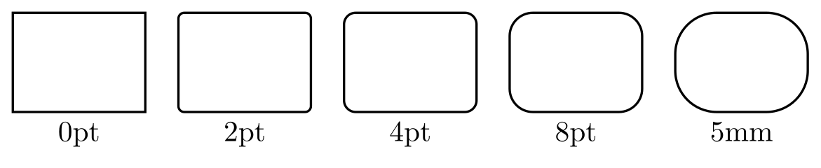
\usepackage{tikz}\begin{tikzpicture}
\foreach \r [count=\i from 0] in {0pt, 2pt, 4pt, 8pt, 5mm} {
\draw[thick, rounded corners=\r] (2*\i,0) rectangle ++(1.6,1.2);
\node[below] at (2*\i+0.8,0) {\r};
}
\end{tikzpicture}Full document
\documentclass[border=4pt]{standalone}
\usepackage{tikz}
\begin{document}
\begin{tikzpicture}
  \foreach \r [count=\i from 0] in {0pt, 2pt, 4pt, 8pt, 5mm} {
    \draw[thick, rounded corners=\r] (2*\i,0) rectangle ++(1.6,1.2);
    \node[below] at (2*\i+0.8,0) {\r};
  }
\end{tikzpicture}
\end{document}Round only some corners
rectangle rounds all four corners or none, so for a tab or a card with only the top corners rounded, draw the outline as lines and switch the rounding on and off along the path. The rule (tested on the picture below): a corner is rounded if rounded corners is in force for the line that reaches it. In the first shape, rounding is switched on before the lines to (0,1.5) and (3,1.5) and switched off with [sharp corners] before the line down, so only the top two corners are round. Close the outline with -- cycle rather than repeating the first point, so the last corner is joined properly.
For a node, the rounded rectangle shape from the shapes.misc library rounds the whole left and right ends into a pill. Each end can be convex (the initial value), concave or none with rounded rectangle left arc and rounded rectangle right arc (also called west arc and east arc), and rounded rectangle arc length (initially 180) flattens the ends; the manual recommends 90 to 180. The same library has chamfered rectangle for cut-off corners.
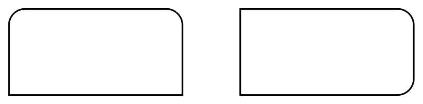
\usepackage{tikz}\begin{tikzpicture}[thick]
% top corners only: rounding is on for the two lines that reach them
\draw (0,0) [rounded corners=8pt] -- (0,1.5) -- (3,1.5)
[sharp corners] -- (3,0) -- cycle;
% right-hand corners only
\draw (4,0) -- (4,1.5) [rounded corners=8pt] -- (7,1.5) -- (7,0)
[sharp corners] -- cycle;
\end{tikzpicture}Full document
\documentclass[border=4pt]{standalone}
\usepackage{tikz}
\begin{document}
\begin{tikzpicture}[thick]
  % top corners only: rounding is on for the two lines that reach them
  \draw (0,0) [rounded corners=8pt] -- (0,1.5) -- (3,1.5)
        [sharp corners] -- (3,0) -- cycle;
  % right-hand corners only
  \draw (4,0) -- (4,1.5) [rounded corners=8pt] -- (7,1.5) -- (7,0)
        [sharp corners] -- cycle;
\end{tikzpicture}
\end{document}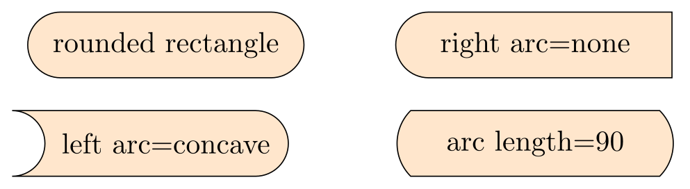
\usepackage{tikz} \usetikzlibrary{shapes.misc}\begin{tikzpicture}[every node/.style={draw, rounded rectangle, fill=orange!20,
minimum width=3.6cm, minimum height=8mm}]
\node at (0,0) {rounded rectangle};
\node[rounded rectangle right arc=none] at (4.5,0) {right arc=none};
\node[rounded rectangle left arc=concave] at (0,-1.2) {left arc=concave};
\node[rounded rectangle arc length=90] at (4.5,-1.2) {arc length=90};
\end{tikzpicture}Full document
\documentclass[border=4pt]{standalone}
\usepackage{tikz}
\usetikzlibrary{shapes.misc}
\begin{document}
\begin{tikzpicture}[every node/.style={draw, rounded rectangle, fill=orange!20,
                                       minimum width=3.6cm, minimum height=8mm}]
  \node at (0,0)    {rounded rectangle};
  \node[rounded rectangle right arc=none] at (4.5,0) {right arc=none};
  \node[rounded rectangle left arc=concave] at (0,-1.2) {left arc=concave};
  \node[rounded rectangle arc length=90] at (4.5,-1.2) {arc length=90};
\end{tikzpicture}
\end{document}A rectangle with text inside
There are two ways to put text in a rectangle. The quick one writes a node inside the rectangle operation: \draw (0,0) rectangle node{centred text} (3,1.5);. TikZ places such a node along the rectangle’s diagonal, halfway by default, which is the centre; node[midway] after the second corner does the same. (The manual’s section on placing nodes on paths still says this only works for lines and curves; current PGF, as in TeX Live 2026, handles rectangles too.)
The more useful one is a node, whose default shape is already a rectangle: \node[draw] (n) {text};. A node sizes itself to its text, keeps the text centred, and has a name, so arrows can end at its border (\draw[->] (a) -- (n);) and other things can be placed at its anchors such as n.north east. Use a path rectangle for a frame or a fixed area, and a node for anything that holds text or is connected to something.
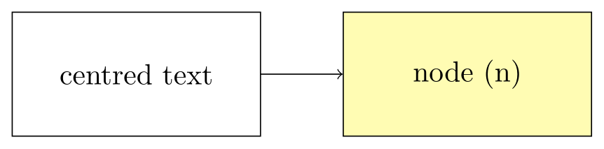
\usepackage{tikz}\begin{tikzpicture}
% a node written inside the rectangle operation lands at its centre
\draw (0,0) rectangle node{centred text} (3,1.5);
% a rectangular node: sized by its text and options, and it has a name
\node[draw, fill=yellow!30, minimum width=3cm, minimum height=1.5cm]
(n) at (5.5,0.75) {node (n)};
\draw[->] (3,0.75) -- (n);
\end{tikzpicture}Full document
\documentclass[border=4pt]{standalone}
\usepackage{tikz}
\begin{document}
\begin{tikzpicture}
  % a node written inside the rectangle operation lands at its centre
  \draw (0,0) rectangle node{centred text} (3,1.5);
  % a rectangular node: sized by its text and options, and it has a name
  \node[draw, fill=yellow!30, minimum width=3cm, minimum height=1.5cm]
    (n) at (5.5,0.75) {node (n)};
  \draw[->] (3,0.75) -- (n);
\end{tikzpicture}
\end{document}Set the size of a rectangle node
A node is as big as its text plus the inner sep, the padding between the text and the border (initially .3333em on every side; inner xsep and inner ysep set the two directions separately). minimum width, minimum height and minimum size (both at once) make the box at least that big, including the inner sep, so boxes with different labels line up. They are minimums: longer text still makes the node grow, as the right-hand box below shows.
Give these lengths a unit. A bare number is read as points, so minimum width=3 asks for 3pt and appears to do nothing. The border is drawn centred on the shape’s outline, so a very thick border adds half its width outside the minimum size; outer sep (by default half the line width) moves the anchors to the outside of that line so arrows stop at the visible edge.
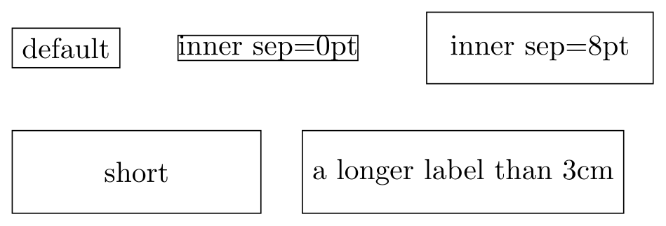
\usepackage{tikz}\begin{tikzpicture}[every node/.style={draw, anchor=west}]
% inner sep = space between the text and the border (default .3333em)
\node at (0,0) {default};
\node[inner sep=0pt] at (2,0) {inner sep=0pt};
\node[inner sep=8pt] at (5,0) {inner sep=8pt};
% minimum width/height = the smallest box; longer text still makes it grow
\node[minimum width=3cm, minimum height=1cm] at (0,-1.5) {short};
\node[minimum width=3cm, minimum height=1cm] at (3.5,-1.5) {a longer label than 3cm};
\end{tikzpicture}Full document
\documentclass[border=4pt]{standalone}
\usepackage{tikz}
\begin{document}
\begin{tikzpicture}[every node/.style={draw, anchor=west}]
  % inner sep = space between the text and the border (default .3333em)
  \node                 at (0,0)   {default};
  \node[inner sep=0pt]  at (2,0)   {inner sep=0pt};
  \node[inner sep=8pt]  at (5,0)   {inner sep=8pt};
  % minimum width/height = the smallest box; longer text still makes it grow
  \node[minimum width=3cm, minimum height=1cm] at (0,-1.5) {short};
  \node[minimum width=3cm, minimum height=1cm] at (3.5,-1.5) {a longer label than 3cm};
\end{tikzpicture}
\end{document}Wrap and align text in the rectangle
text width=3cm makes the text a paragraph of that width, wrapped automatically and ragged right (the manual’s default is align=left). Add align=center, right, justify or flush center to change the alignment. Without a text width you can still break lines by hand with \\, but only if align is set; otherwise the \\ is dropped and the lines run together.
The node ends up wider than the text width by twice the inner xsep. For a box exactly 3 cm wide with wrapped text, set text width=3cm, inner xsep=0pt, or use minimum width=3cm with a slightly smaller text width. There is more on fonts, bold text, titles and callouts on the TikZ text box page.

\usepackage{tikz}\begin{tikzpicture}[every node/.style={draw, anchor=north west}]
\node[text width=3cm] at (0,0)
{Long text wraps at 3\,cm and is ragged right by default.};
\node[text width=3cm, align=center] at (3.8,0)
{With \texttt{align=center} the wrapped lines are centred.};
\node[align=right] at (7.6,0)
{No text width:\\break lines\\yourself with \textbackslash\textbackslash};
\end{tikzpicture}Full document
\documentclass[border=4pt]{standalone}
\usepackage{tikz}
\begin{document}
\begin{tikzpicture}[every node/.style={draw, anchor=north west}]
  \node[text width=3cm] at (0,0)
    {Long text wraps at 3\,cm and is ragged right by default.};
  \node[text width=3cm, align=center] at (3.8,0)
    {With \texttt{align=center} the wrapped lines are centred.};
  \node[align=right] at (7.6,0)
    {No text width:\\break lines\\yourself with \textbackslash\textbackslash};
\end{tikzpicture}
\end{document}Fill, border colour and transparency
fill=yellow and draw=red set the two colours separately; a bare colour such as red sets both, and the text colour of nodes. Any xcolor expression works: blue!30 is 30% blue mixed with white, green!50!black a dark green.
For transparency, fill opacity=0.3 makes only the filling see-through, draw opacity only the border, and opacity both. In the overlap on the right the blue rectangle shows through the red one. In a node, fill opacity also fades the text unless you add text opacity=1.
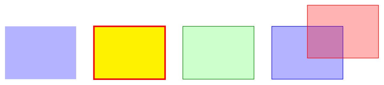
\usepackage{tikz}\begin{tikzpicture}
\fill[blue!30] (0,0) rectangle (2,1.5); % fill, no border
\draw[red, very thick, fill=yellow] (2.5,0) rectangle (4.5,1.5); % border and fill
\filldraw[fill=green!20, draw=green!50!black] (5,0) rectangle (7,1.5);
% fill opacity lets what is underneath show through; the border stays solid
\draw[blue, fill=blue, fill opacity=0.3] (7.5,0) rectangle (9.5,1.5);
\draw[red, fill=red, fill opacity=0.3] (8.5,0.6) rectangle (10.5,2.1);
\end{tikzpicture}Full document
\documentclass[border=4pt]{standalone}
\usepackage{tikz}
\begin{document}
\begin{tikzpicture}
  \fill[blue!30] (0,0) rectangle (2,1.5);                           % fill, no border
  \draw[red, very thick, fill=yellow] (2.5,0) rectangle (4.5,1.5);  % border and fill
  \filldraw[fill=green!20, draw=green!50!black] (5,0) rectangle (7,1.5);
  % fill opacity lets what is underneath show through; the border stays solid
  \draw[blue, fill=blue, fill opacity=0.3] (7.5,0) rectangle (9.5,1.5);
  \draw[red, fill=red, fill opacity=0.3] (8.5,0.6) rectangle (10.5,2.1);
\end{tikzpicture}
\end{document}Squares
A square is a rectangle with equal sides: \draw (0,0) rectangle (1.5,1.5); or (0,0) rectangle ++(1.5,1.5). As a node, minimum size=1.5cm sets both minimums, which gives a square as long as the text fits inside; a label wider than the minimum turns it back into a rectangle. A \foreach loop repeats squares for grids, scales and legends.
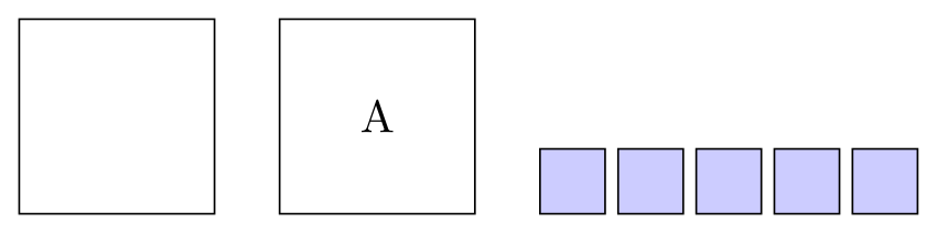
\usepackage{tikz}\begin{tikzpicture}
\draw (0,0) rectangle (1.5,1.5); % equal width and height
\node[draw, minimum size=1.5cm] at (2.75,0.75) {A}; % a square node
\foreach \x in {0,...,4} % a row of squares
\draw[fill=blue!20] (4+0.6*\x,0) rectangle ++(0.5,0.5);
\end{tikzpicture}Full document
\documentclass[border=4pt]{standalone}
\usepackage{tikz}
\begin{document}
\begin{tikzpicture}
  \draw (0,0) rectangle (1.5,1.5);                      % equal width and height
  \node[draw, minimum size=1.5cm] at (2.75,0.75) {A};   % a square node
  \foreach \x in {0,...,4}                              % a row of squares
    \draw[fill=blue!20] (4+0.6*\x,0) rectangle ++(0.5,0.5);
\end{tikzpicture}
\end{document}A rectangle around other nodes (fit library)
To frame a group, load \usetikzlibrary{fit} and give an empty node the option fit=(a) (b) (c): it becomes the smallest box containing the north, south, east and west anchors of those nodes (or the coordinates you list), plus its own inner sep, so inner sep=8pt controls the margin. label=above:Pipeline adds a title.
The fit node is drawn after the nodes it surrounds, so a fill on it would cover them. For a shaded group background, put the fit node in a scope with on background layer from the backgrounds library, shown on the text box page.
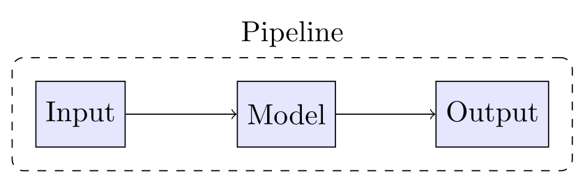
\usepackage{tikz} \usetikzlibrary{fit}\begin{tikzpicture}[box/.style={draw, fill=blue!10, minimum height=8mm}]
\node[box] (a) at (0,0) {Input};
\node[box] (b) at (2.5,0) {Model};
\node[box] (c) at (5,0) {Output};
\draw[->] (a) -- (b);
\draw[->] (b) -- (c);
\node[draw, dashed, rounded corners, inner sep=8pt,
fit=(a) (b) (c), label=above:Pipeline] {};
\end{tikzpicture}Full document
\documentclass[border=4pt]{standalone}
\usepackage{tikz}
\usetikzlibrary{fit}
\begin{document}
\begin{tikzpicture}[box/.style={draw, fill=blue!10, minimum height=8mm}]
  \node[box] (a) at (0,0)   {Input};
  \node[box] (b) at (2.5,0) {Model};
  \node[box] (c) at (5,0)   {Output};
  \draw[->] (a) -- (b);
  \draw[->] (b) -- (c);
  \node[draw, dashed, rounded corners, inner sep=8pt,
        fit=(a) (b) (c), label=above:Pipeline] {};
\end{tikzpicture}
\end{document}Common errors and how to fix them
| LaTeX says (or you see) | Cause and fix |
|---|---|
| Package pgfkeys Error: I do not know the key '/tikz/rounded rectangle' and I am going to ignore it. Perhaps you misspelled it. | The rounded rectangle shape is in a library: add \usetikzlibrary{shapes.misc} to the preamble. If you only wanted round corners, the option is rounded corners, which needs no library. |
| Package pgfkeys Error: I do not know the key '/tikz/fit', to which you passed '(a)', and I am going to ignore it. Perhaps you misspelled it. | Add \usetikzlibrary{fit} to the preamble. |
| Package tikz Error: Giving up on this path. Did you forget a semicolon? | Every \draw, \fill, \path and \node ends with a semicolon; add the missing ; after the last coordinate or node text. |
| The rounded outline crosses itself and looks like a bow tie | The rounded corners inset is larger than half the shorter side (for example rounded corners=1cm on a rectangle 1.2cm high). Use at most half of it, which gives semicircular ends, or the rounded rectangle node shape. |
| minimum width=3 (or minimum height=2) seems to have no effect | A length without a unit is read as points, so this asks for 3pt. Write minimum width=3cm. |
| The node is wider than its text width | text width is the width of the text; the inner sep is added on both sides. Use inner xsep=0pt, or a smaller text width together with minimum width. |
| Lines broken with \\ run together in one line | Inside a node, \\ only breaks the line when align (or text width) is set: add align=center, left or right. |
Frequently asked questions
How do I make a rectangle with rounded corners in TikZ?
Add rounded corners to the path options: \draw[rounded corners] (0,0) rectangle (3,2); uses the default 4pt; \draw[rounded corners=8pt] … sets the radius. For a node, write \node[draw, rounded corners] {Text};. To round every rectangle in a picture, put the option on the tikzpicture: \begin{tikzpicture}[rounded corners=3pt].
How do I round only one or two corners of a rectangle?
Draw the outline as lines and switch the rounding on and off along the path. A corner is rounded when rounded corners is in force for the line that reaches it, so \draw (0,0) [rounded corners=8pt] -- (0,1.5) -- (3,1.5) [sharp corners] -- (3,0) -- cycle; rounds only the two top corners. For a node with one flat end, the rounded rectangle shape from shapes.misc takes rounded rectangle left arc=none or right arc=none.
How do I put text in the centre of a TikZ rectangle?
Either write a node inside the rectangle operation, \draw (0,0) rectangle node{Text} (3,2);, which places it at the centre, or draw the rectangle as a node: \node[draw, minimum width=3cm, minimum height=2cm] {Text};. The node version can be named, so arrows and labels can attach to it.
How do I set the exact size of a rectangle node?
Use minimum width and minimum height (with units, such as 3cm), which include the inner sep. The node only grows beyond them if its text needs more room. For wrapped text of a fixed width, use text width; the node is then text width plus twice the inner xsep wide.
What is the default radius of rounded corners in TikZ?
4pt. The value is the inset, the distance from the corner at which the arc starts, and it is not scaled by scale=. For the right-angled corners of a rectangle it equals the radius of the quarter circles.
How do I draw a rotated rectangle?
Add rotate to the path: \draw[rotate=30] (0,0) rectangle (2,1); turns it about the origin, and rotate around={30:(1,0.5)} turns it about its own centre. For a node, rotate=30 rotates the box and its text together.
References
- PGF/TikZ manual, §14.4 The Rectangle Operationtikz.dev
- PGF/TikZ manual, §14.5 Rounding Cornerstikz.dev
- PGF/TikZ manual, §17.2.3 Common Options: Separations, Margins, Padding and Border Rotationtikz.dev
- PGF/TikZ manual, §17.4.3 Text Parameters: Alignment and Width for Multi-Line Texttikz.dev
- PGF/TikZ manual, §15.5 Filling a Pathtikz.dev
- PGF/TikZ manual, §23.2 Specifying a Uniform Opacitytikz.dev
- PGF/TikZ manual, §71.8 Miscellaneous Shapes (rounded rectangle, chamfered rectangle)tikz.dev
- PGF/TikZ manual, §54 Fitting Librarytikz.dev
- PGF/TikZ manual, §25.3 Coordinate Transformations (rotate, rotate around)tikz.dev
- pgf package (TikZ) on CTAN, with the full manual as PDFctan.org
The facts on this page were checked against these sources, and every picture is the code with it typeset with TeX Live 2026. Code on this page: CC0 1.0, copy it freely.
Try the code in your browserEvery snippet on this page opens in the free TikZ editor: it is typeset with TeX Live as you type, with errors pointed at their line.
Open the TikZ editor