How to draw circles, ellipses and arcs in TikZ
Quick answer
\draw (0,0) circle[radius=1];: the coordinate is the centre (the older circle (1) still works). An ellipse takes two radii: \draw (0,0) ellipse[x radius=2, y radius=1];. An arc starts at the current point, not at the centre: \draw (1,0) arc[start angle=0, end angle=90, radius=1]; draws a quarter circle counter-clockwise around (0,0). For marked angles in geometry figures, use the angles library: pic[draw] {angle=A--B--C}.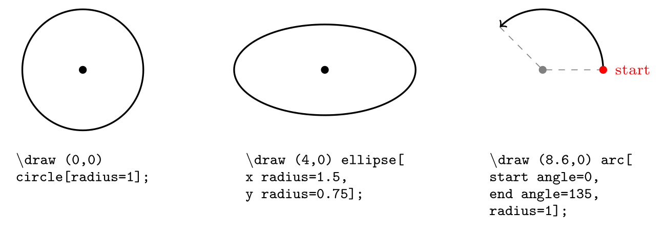
\usepackage{tikz}\begin{tikzpicture}[code/.style={font=\ttfamily\scriptsize, align=left, anchor=north},
dot/.style={circle, fill, inner sep=1.3pt}]
\draw[thick] (0,0) circle[radius=1];
\node[dot] at (0,0) {};
\node[code] at (0,-1.25) {\textbackslash draw (0,0)\\ circle[radius=1];};
\draw[thick] (4,0) ellipse[x radius=1.5, y radius=0.75];
\node[dot] at (4,0) {};
\node[code] at (4,-1.25) {\textbackslash draw (4,0) ellipse[\\ x radius=1.5,\\ y radius=0.75];};
\draw[gray, dashed] (8.6,0) -- (7.6,0) -- ++(135:1);
\draw[thick, ->] (8.6,0) arc[start angle=0, end angle=135, radius=1];
\node[dot, red, label={[red, font=\scriptsize]right:start}] at (8.6,0) {};
\node[dot, gray] at (7.6,0) {};
\node[code] at (7.9,-1.25) {\textbackslash draw (8.6,0) arc[\\ start angle=0,\\ end angle=135,\\ radius=1];};
\end{tikzpicture}Full document
\documentclass[border=4pt]{standalone}
\usepackage{tikz}
\begin{document}
\begin{tikzpicture}[code/.style={font=\ttfamily\scriptsize, align=left, anchor=north},
                    dot/.style={circle, fill, inner sep=1.3pt}]
  \draw[thick] (0,0) circle[radius=1];
  \node[dot] at (0,0) {};
  \node[code] at (0,-1.25) {\textbackslash draw (0,0)\\ circle[radius=1];};

  \draw[thick] (4,0) ellipse[x radius=1.5, y radius=0.75];
  \node[dot] at (4,0) {};
  \node[code] at (4,-1.25) {\textbackslash draw (4,0) ellipse[\\ x radius=1.5,\\ y radius=0.75];};

  \draw[gray, dashed] (8.6,0) -- (7.6,0) -- ++(135:1);
  \draw[thick, ->] (8.6,0) arc[start angle=0, end angle=135, radius=1];
  \node[dot, red, label={[red, font=\scriptsize]right:start}] at (8.6,0) {};
  \node[dot, gray] at (7.6,0) {};
  \node[code] at (7.9,-1.25) {\textbackslash draw (8.6,0) arc[\\ start angle=0,\\ end angle=135,\\ radius=1];};
\end{tikzpicture}
\end{document}Contents
Draw a circle: circle[radius=…]
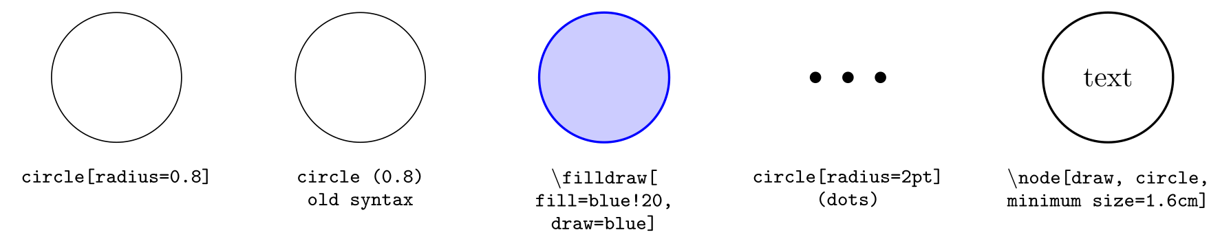
circle is a path operation that adds a circle around the current point, which becomes (and stays) its centre: \draw (2,1) circle[radius=1.5];. \fill or \filldraw[fill=…, draw=…] fills it, and at= inside the options puts the centre elsewhere. A small filled circle is the usual way to draw a dot: \fill (p) circle[radius=2pt];.
The older form circle (1) (radius in parentheses) still works and appears in most code online. TikZ decides by what follows: if circle is directly followed by an opening parenthesis, it reads the old syntax, which must contain a single number or length. The manual prefers the key form because parentheses normally hold coordinates.
A radius can also be set once for a picture or scope, [radius=2pt], and then circle needs no options. If no radius is set anywhere, TikZ draws nothing and reports nothing, because x radius and y radius start at 0pt. For a circle with text inside, connected to other things, use a node instead: \node[draw, circle, minimum size=1.6cm] {text}; (see nodes).
\usepackage{tikz}\begin{tikzpicture}[code/.style={font=\ttfamily\scriptsize, align=center, anchor=north}]
\draw (0,0) circle[radius=0.8];
\node[code] at (0,-1) {circle[radius=0.8]};
\draw (3,0) circle (0.8);
\node[code] at (3,-1) {circle (0.8)\\old syntax};
\filldraw[fill=blue!20, draw=blue, thick] (6,0) circle[radius=0.8];
\node[code] at (6,-1) {\textbackslash filldraw[\\fill=blue!20,\\draw=blue]};
\foreach \x in {8.6,9,9.4} \fill (\x,0) circle[radius=2pt];
\node[code] at (9,-1) {circle[radius=2pt]\\(dots)};
\node[draw, circle, thick, minimum size=1.6cm] at (12.2,0) {text};
\node[code] at (12.2,-1) {\textbackslash node[draw, circle,\\minimum size=1.6cm]};
\end{tikzpicture}Full document
\documentclass[border=4pt]{standalone}
\usepackage{tikz}
\begin{document}
\begin{tikzpicture}[code/.style={font=\ttfamily\scriptsize, align=center, anchor=north}]
  \draw (0,0) circle[radius=0.8];
  \node[code] at (0,-1) {circle[radius=0.8]};

  \draw (3,0) circle (0.8);
  \node[code] at (3,-1) {circle (0.8)\\old syntax};

  \filldraw[fill=blue!20, draw=blue, thick] (6,0) circle[radius=0.8];
  \node[code] at (6,-1) {\textbackslash filldraw[\\fill=blue!20,\\draw=blue]};

  \foreach \x in {8.6,9,9.4} \fill (\x,0) circle[radius=2pt];
  \node[code] at (9,-1) {circle[radius=2pt]\\(dots)};

  \node[draw, circle, thick, minimum size=1.6cm] at (12.2,0) {text};
  \node[code] at (12.2,-1) {\textbackslash node[draw, circle,\\minimum size=1.6cm]};
\end{tikzpicture}
\end{document}Draw an ellipse
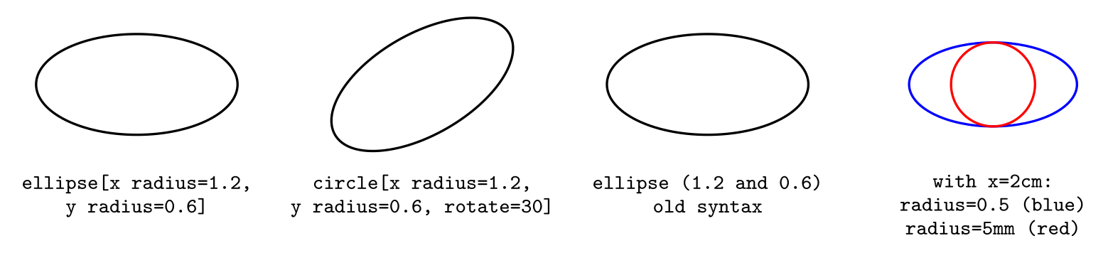
ellipse is the same operation as circle with two radii: \draw (0,0) ellipse[x radius=1.2, y radius=0.6];, which is exactly circle[x radius=1.2, y radius=0.6]. The old form is ellipse (1.2 and 0.6), with and between the radii; a comma, ellipse (2,1), fails with Missing number, treated as zero. To tilt an ellipse, put rotate=30 in its options; it turns only that ellipse, around its centre.
Radii without a unit are measured in the picture’s coordinate system, like coordinates. That matters if you change the units: with x=2cm, circle[radius=0.5] is 2 cm wide but 1 cm high, an ellipse, while radius=5mm stays a circle. Likewise scale=2 doubles circles, and xscale=2 turns them into ellipses.
\usepackage{tikz}\begin{tikzpicture}[code/.style={font=\ttfamily\scriptsize, align=center, anchor=north}]
\draw[thick] (0,0) ellipse[x radius=1.2, y radius=0.6];
\node[code] at (0,-0.95) {ellipse[x radius=1.2,\\y radius=0.6]};
\draw[thick] (3.4,0) circle[x radius=1.2, y radius=0.6, rotate=30];
\node[code] at (3.4,-0.95) {circle[x radius=1.2,\\y radius=0.6, rotate=30]};
\draw[thick] (6.8,0) ellipse (1.2 and 0.6);
\node[code] at (6.8,-0.95) {ellipse (1.2 and 0.6)\\old syntax};
\begin{scope}[xshift=10.2cm, x=2cm]
\draw[thick, blue] (0,0) circle[radius=0.5];
\draw[thick, red] (0,0) circle[radius=5mm];
\end{scope}
\node[code] at (10.2,-0.95) {with x=2cm:\\radius=0.5 (blue)\\radius=5mm (red)};
\end{tikzpicture}Full document
\documentclass[border=4pt]{standalone}
\usepackage{tikz}
\begin{document}
\begin{tikzpicture}[code/.style={font=\ttfamily\scriptsize, align=center, anchor=north}]
  \draw[thick] (0,0) ellipse[x radius=1.2, y radius=0.6];
  \node[code] at (0,-0.95) {ellipse[x radius=1.2,\\y radius=0.6]};

  \draw[thick] (3.4,0) circle[x radius=1.2, y radius=0.6, rotate=30];
  \node[code] at (3.4,-0.95) {circle[x radius=1.2,\\y radius=0.6, rotate=30]};

  \draw[thick] (6.8,0) ellipse (1.2 and 0.6);
  \node[code] at (6.8,-0.95) {ellipse (1.2 and 0.6)\\old syntax};

  \begin{scope}[xshift=10.2cm, x=2cm]
    \draw[thick, blue] (0,0) circle[radius=0.5];
    \draw[thick, red]  (0,0) circle[radius=5mm];
  \end{scope}
  \node[code] at (10.2,-0.95) {with x=2cm:\\radius=0.5 (blue)\\radius=5mm (red)};
\end{tikzpicture}
\end{document}Draw an arc: start angle, end angle, radius
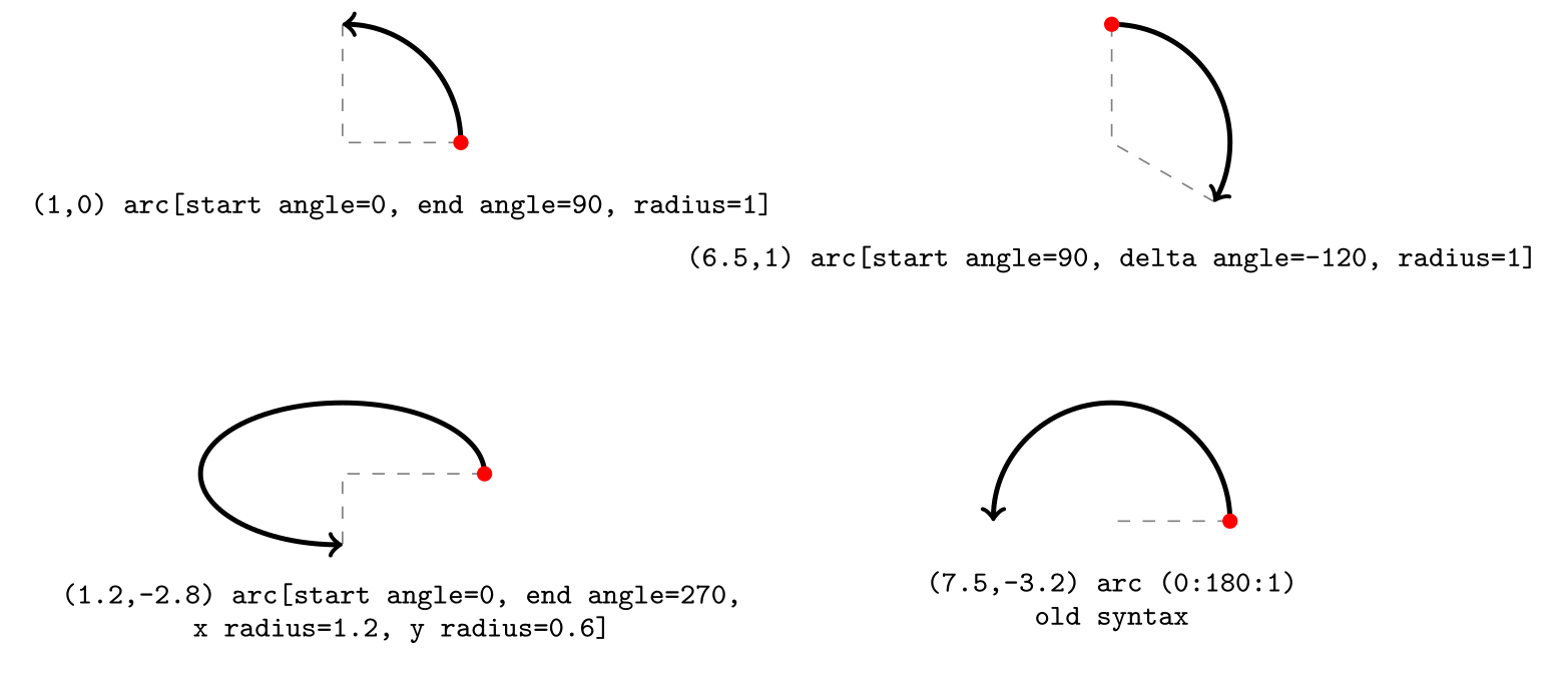
arc[start angle=…, end angle=…, radius=…] adds part of a circle (or of an ellipse, with x radius and y radius) to the path. The key point: the arc starts at the current point, the point on the circle at the start angle. The centre is never given; it lies one radius from the start point, in the direction opposite to the start angle. So (1,0) arc[start angle=0, end angle=90, radius=1] is a quarter circle around (0,0) from (1,0) to (0,1), and the path continues from (0,1).
Angles are in degrees, measured counter-clockwise from the positive x axis. The arc runs from the start angle to the end angle, counter-clockwise when the end angle is larger and clockwise when it is smaller. Instead of an end angle you can give delta angle: delta angle=-120 draws 120° clockwise. If one of the three keys is missing it is computed from the other two; if all three are given, delta angle is ignored.
The short form arc (0:90:1) means start angle, end angle and radius, and arc (0:270:1.2 and 0.6) is elliptical. The manual says the key syntax “should be preferred” because it is easier to read, and the TikZ source calls the parenthesised syntax deprecated, but it still works. Mixing a length and a plain number for the two radii, such as x radius=1cm, y radius=0.5, stops with You cannot mix dimensions and dimensionless values in an arc.
\usepackage{tikz}\begin{tikzpicture}[code/.style={font=\ttfamily\scriptsize, align=center, anchor=north},
start/.style={circle, fill=red, inner sep=1.3pt},
centre/.style={gray, dashed}]
% start and end angle: counter-clockwise from the current point
\draw[centre] (1,0) -- (0,0) -- (0,1);
\draw[very thick, ->] (1,0) arc[start angle=0, end angle=90, radius=1];
\node[start] at (1,0) {};
\node[code] at (0.5,-0.3) {(1,0) arc[start angle=0, end angle=90, radius=1]};
% a negative delta angle runs clockwise
\draw[centre] (6.5,1) -- (6.5,0) -- ++(-30:1);
\draw[very thick, ->] (6.5,1) arc[start angle=90, delta angle=-120, radius=1];
\node[start] at (6.5,1) {};
\node[code] at (6.5,-0.75) {(6.5,1) arc[start angle=90, delta angle=-120, radius=1]};
% two radii make an elliptical arc
\draw[centre] (1.2,-2.8) -- (0,-2.8) -- (0,-3.4);
\draw[very thick, ->] (1.2,-2.8) arc[start angle=0, end angle=270, x radius=1.2, y radius=0.6];
\node[start] at (1.2,-2.8) {};
\node[code] at (0.5,-3.6) {(1.2,-2.8) arc[start angle=0, end angle=270,\\x radius=1.2, y radius=0.6]};
% the old syntax: (start angle:end angle:radius)
\draw[centre] (7.5,-3.2) -- (6.5,-3.2);
\draw[very thick, ->] (7.5,-3.2) arc (0:180:1);
\node[start] at (7.5,-3.2) {};
\node[code] at (6.5,-3.5) {(7.5,-3.2) arc (0:180:1)\\old syntax};
\end{tikzpicture}Full document
\documentclass[border=4pt]{standalone}
\usepackage{tikz}
\begin{document}
\begin{tikzpicture}[code/.style={font=\ttfamily\scriptsize, align=center, anchor=north},
                    start/.style={circle, fill=red, inner sep=1.3pt},
                    centre/.style={gray, dashed}]
  % start and end angle: counter-clockwise from the current point
  \draw[centre] (1,0) -- (0,0) -- (0,1);
  \draw[very thick, ->] (1,0) arc[start angle=0, end angle=90, radius=1];
  \node[start] at (1,0) {};
  \node[code] at (0.5,-0.3) {(1,0) arc[start angle=0, end angle=90, radius=1]};

  % a negative delta angle runs clockwise
  \draw[centre] (6.5,1) -- (6.5,0) -- ++(-30:1);
  \draw[very thick, ->] (6.5,1) arc[start angle=90, delta angle=-120, radius=1];
  \node[start] at (6.5,1) {};
  \node[code] at (6.5,-0.75) {(6.5,1) arc[start angle=90, delta angle=-120, radius=1]};

  % two radii make an elliptical arc
  \draw[centre] (1.2,-2.8) -- (0,-2.8) -- (0,-3.4);
  \draw[very thick, ->] (1.2,-2.8) arc[start angle=0, end angle=270, x radius=1.2, y radius=0.6];
  \node[start] at (1.2,-2.8) {};
  \node[code] at (0.5,-3.6) {(1.2,-2.8) arc[start angle=0, end angle=270,\\x radius=1.2, y radius=0.6]};

  % the old syntax: (start angle:end angle:radius)
  \draw[centre] (7.5,-3.2) -- (6.5,-3.2);
  \draw[very thick, ->] (7.5,-3.2) arc (0:180:1);
  \node[start] at (7.5,-3.2) {};
  \node[code] at (6.5,-3.5) {(7.5,-3.2) arc (0:180:1)\\old syntax};
\end{tikzpicture}
\end{document}An arc around a given centre
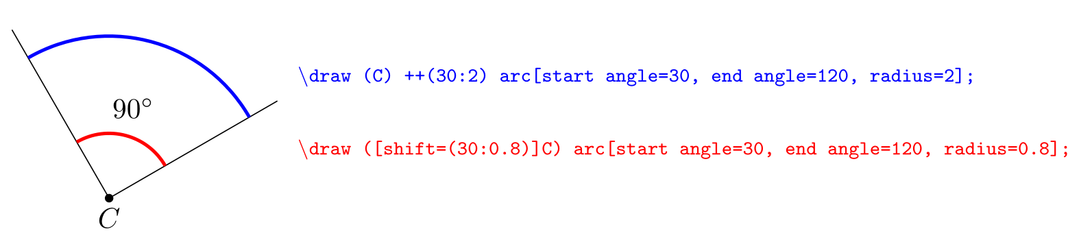
Because an arc starts on the circle, you first move from the centre to the start point. Two ways, both shown below:
\draw (C) ++(30:2) arc[start angle=30, end angle=120, radius=2];:++(30:2)is a polar step of length 2 at 30° from C, exactly the start of the arc.\draw ([shift=(30:2)]C) arc[…];: the same point written as one coordinate, which is handy when the arc is part of a longer path.
The start angle in the polar step and in the arc must agree, and so must the radius, or the arc is drawn around a different centre. This is also how to mark an angle by hand; for geometry figures the angles library below does it for you. Nodes can be placed on arcs with pos (0 at the start, 1 at the end): arc[…] node[pos=0.5, above] {label}.
\usepackage{tikz}\begin{tikzpicture}[code/.style={font=\ttfamily\scriptsize, anchor=west}]
\coordinate (C) at (0,0);
\draw (C) -- (30:2.4) (C) -- (120:2.4);
\fill (C) circle[radius=1.5pt] node[below] {$C$};
% move from the centre to the start of the arc with ++(angle:radius)
\draw[very thick, blue] (C) ++(30:2) arc[start angle=30, end angle=120, radius=2];
% or shift the start point: ([shift=(angle:radius)]C)
\draw[very thick, red] ([shift=(30:0.8)]C) arc[start angle=30, end angle=120, radius=0.8];
\node at (75:1.15) {$90^\circ$};
\node[code, text=blue] at (2.2,1.5) {\textbackslash draw (C) ++(30:2) arc[start angle=30, end angle=120, radius=2];};
\node[code, text=red] at (2.2,0.6) {\textbackslash draw ([shift=(30:0.8)]C) arc[start angle=30, end angle=120, radius=0.8];};
\end{tikzpicture}Full document
\documentclass[border=4pt]{standalone}
\usepackage{tikz}
\begin{document}
\begin{tikzpicture}[code/.style={font=\ttfamily\scriptsize, anchor=west}]
  \coordinate (C) at (0,0);
  \draw (C) -- (30:2.4) (C) -- (120:2.4);
  \fill (C) circle[radius=1.5pt] node[below] {$C$};

  % move from the centre to the start of the arc with ++(angle:radius)
  \draw[very thick, blue] (C) ++(30:2) arc[start angle=30, end angle=120, radius=2];
  % or shift the start point: ([shift=(angle:radius)]C)
  \draw[very thick, red] ([shift=(30:0.8)]C) arc[start angle=30, end angle=120, radius=0.8];
  \node at (75:1.15) {$90^\circ$};

  \node[code, text=blue] at (2.2,1.5) {\textbackslash draw (C) ++(30:2) arc[start angle=30, end angle=120, radius=2];};
  \node[code, text=red] at (2.2,0.6) {\textbackslash draw ([shift=(30:0.8)]C) arc[start angle=30, end angle=120, radius=0.8];};
\end{tikzpicture}
\end{document}Half circles and semicircles
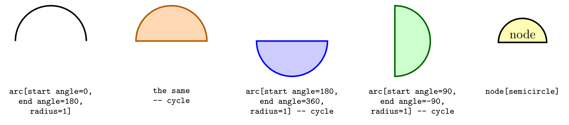
A half circle is an arc of 180°. (1,0) arc[start angle=0, end angle=180, radius=1] is the upper half of the unit circle; add -- cycle to close it along the diameter, which is needed for a clean filled half disc. Start at 180 and end at 360 for the lower half, and go from 90 to −90 for the right half (clockwise, because the end angle is smaller). For a half circle that holds text, the semicircle node shape from shapes.geometric fits itself around the text and has anchors such as apex and chord center.
\usepackage{tikz} \usetikzlibrary{shapes.geometric}\begin{tikzpicture}[code/.style={font=\ttfamily\scriptsize, align=center, anchor=north}]
% upper half: from 0 to 180 degrees around (0,0)
\draw[very thick] (1,0) arc[start angle=0, end angle=180, radius=1];
\node[code] at (0,-1.2) {arc[start angle=0,\\end angle=180,\\radius=1]};
% close it along the diameter to fill it
\filldraw[fill=orange!30, draw=orange!70!black, very thick]
(4.4,0) arc[start angle=0, end angle=180, radius=1] -- cycle;
\node[code] at (3.4,-1.2) {the same\\ -- cycle};
% lower half around (6.8,0)
\filldraw[fill=blue!20, draw=blue, very thick]
(5.8,0) arc[start angle=180, end angle=360, radius=1] -- cycle;
\node[code] at (6.8,-1.2) {arc[start angle=180,\\end angle=360,\\radius=1] -- cycle};
% right half around (9.7,0)
\filldraw[fill=green!20, draw=green!40!black, very thick]
(9.7,1) arc[start angle=90, end angle=-90, radius=1] -- cycle;
\node[code] at (10.2,-1.2) {arc[start angle=90,\\end angle=-90,\\radius=1] -- cycle};
\node[semicircle, draw, very thick, fill=yellow!30] at (13.3,0.2) {node};
\node[code] at (13.3,-1.2) {node[semicircle]};
\end{tikzpicture}Full document
\documentclass[border=4pt]{standalone}
\usepackage{tikz}
\usetikzlibrary{shapes.geometric}
\begin{document}
\begin{tikzpicture}[code/.style={font=\ttfamily\scriptsize, align=center, anchor=north}]
  % upper half: from 0 to 180 degrees around (0,0)
  \draw[very thick] (1,0) arc[start angle=0, end angle=180, radius=1];
  \node[code] at (0,-1.2) {arc[start angle=0,\\end angle=180,\\radius=1]};

  % close it along the diameter to fill it
  \filldraw[fill=orange!30, draw=orange!70!black, very thick]
    (4.4,0) arc[start angle=0, end angle=180, radius=1] -- cycle;
  \node[code] at (3.4,-1.2) {the same\\ -- cycle};

  % lower half around (6.8,0)
  \filldraw[fill=blue!20, draw=blue, very thick]
    (5.8,0) arc[start angle=180, end angle=360, radius=1] -- cycle;
  \node[code] at (6.8,-1.2) {arc[start angle=180,\\end angle=360,\\radius=1] -- cycle};

  % right half around (9.7,0)
  \filldraw[fill=green!20, draw=green!40!black, very thick]
    (9.7,1) arc[start angle=90, end angle=-90, radius=1] -- cycle;
  \node[code] at (10.2,-1.2) {arc[start angle=90,\\end angle=-90,\\radius=1] -- cycle};

  \node[semicircle, draw, very thick, fill=yellow!30] at (13.3,0.2) {node};
  \node[code] at (13.3,-1.2) {node[semicircle]};
\end{tikzpicture}
\end{document}Sectors, pie charts and ring segments
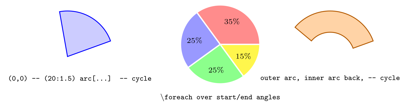
A sector (pie slice) is a closed path: from the centre out to the circle, along the arc, and back. \filldraw (0,0) -- (20:1.5) arc[start angle=20, end angle=100, radius=1.5] -- cycle;; the polar coordinate (20:1.5) is the start of the arc. A \foreach over start and end angles makes a pie chart, and the label of each slice goes at the middle angle, ({(\a+\b)/2}:0.85), slightly inside the radius. A white, thick border separates the slices.
For a ring segment, as in donut charts or gauges, draw the outer arc, step inwards along the radius, and draw the inner arc back with start and end swapped, then close with -- cycle. For real data, the pgf-pie and wheelchart packages draw labelled pie and donut charts with legends.
\usepackage{tikz}\begin{tikzpicture}[code/.style={font=\ttfamily\scriptsize, align=center, anchor=north}]
% one sector (pie slice): centre, line out, arc, back to the centre
\filldraw[fill=blue!20, draw=blue, thick]
(0,0) -- (20:1.5) arc[start angle=20, end angle=100, radius=1.5] -- cycle;
\node[code] at (0.4,-0.5) {(0,0) -- (20:1.5) arc[...] -- cycle};
% a pie chart from a list of start/end angles
\foreach \a/\b/\c/\t in {0/126/red!45/35\%, 126/216/blue!40/25\%,
216/306/green!45/25\%, 306/360/yellow!70/15\%} {
\filldraw[fill=\c, draw=white, very thick]
(5,0.4) -- ++(\a:1.3) arc[start angle=\a, end angle=\b, radius=1.3] -- cycle;
\path (5,0.4) ++({(\a+\b)/2}:0.85) node[font=\scriptsize] {\t};
}
\node[code] at (5,-1.1) {\textbackslash foreach over start/end angles};
% a ring segment: outer arc one way, inner arc back
\filldraw[fill=orange!35, draw=orange!70!black, thick]
(8.6,0) ++(20:1.5) arc[start angle=20, end angle=140, radius=1.5]
-- ++(140:-0.7) arc[start angle=140, end angle=20, radius=0.8] -- cycle;
\node[code] at (8.6,-0.5) {outer arc, inner arc back, -- cycle};
\end{tikzpicture}Full document
\documentclass[border=4pt]{standalone}
\usepackage{tikz}
\begin{document}
\begin{tikzpicture}[code/.style={font=\ttfamily\scriptsize, align=center, anchor=north}]
  % one sector (pie slice): centre, line out, arc, back to the centre
  \filldraw[fill=blue!20, draw=blue, thick]
    (0,0) -- (20:1.5) arc[start angle=20, end angle=100, radius=1.5] -- cycle;
  \node[code] at (0.4,-0.5) {(0,0) -- (20:1.5) arc[...] -- cycle};

  % a pie chart from a list of start/end angles
  \foreach \a/\b/\c/\t in {0/126/red!45/35\%, 126/216/blue!40/25\%,
                           216/306/green!45/25\%, 306/360/yellow!70/15\%} {
    \filldraw[fill=\c, draw=white, very thick]
      (5,0.4) -- ++(\a:1.3) arc[start angle=\a, end angle=\b, radius=1.3] -- cycle;
    \path (5,0.4) ++({(\a+\b)/2}:0.85) node[font=\scriptsize] {\t};
  }
  \node[code] at (5,-1.1) {\textbackslash foreach over start/end angles};

  % a ring segment: outer arc one way, inner arc back
  \filldraw[fill=orange!35, draw=orange!70!black, thick]
    (8.6,0) ++(20:1.5) arc[start angle=20, end angle=140, radius=1.5]
    -- ++(140:-0.7) arc[start angle=140, end angle=20, radius=0.8] -- cycle;
  \node[code] at (8.6,-0.5) {outer arc, inner arc back, -- cycle};
\end{tikzpicture}
\end{document}An arc between two points
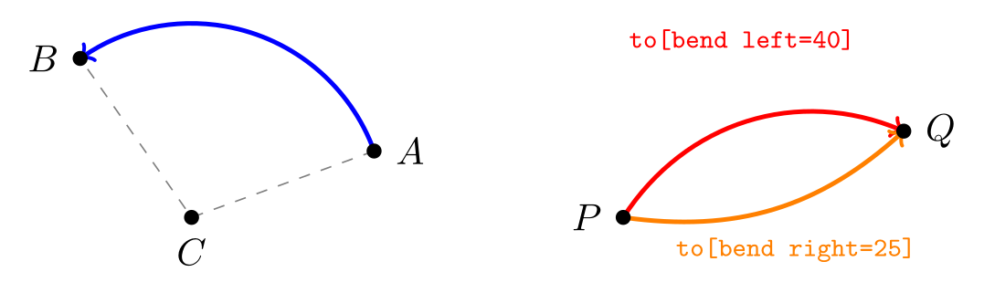
TikZ has no “arc from A to B” operation, because two points and a radius do not fix the arc uniquely. If you know the centre C, compute the start angle, end angle and radius with the calc library and the let operation: atan2(\y1,\x1) is the angle of the vector from C to A and veclen(\x1,\y1) its length. The arc then starts at A and ends at B exactly if B is as far from C as A; otherwise it ends on the same circle, at B’s angle. If the arc runs the wrong way round, add 360 to the end angle (or subtract it).
If you only need a curved connection rather than a true circular arc, to[bend left=40] (or bend right) bends a line between any two points or nodes, with the angle at which it leaves and arrives. It is a Bézier curve, which is indistinguishable from an arc for small bends.
\usepackage{tikz} \usetikzlibrary{calc}\begin{tikzpicture}[dot/.style={circle, fill, inner sep=1.4pt}]
% a circular arc from A to B around a known centre C
\coordinate (C) at (0,0);
\coordinate (A) at (20:1.8);
\coordinate (B) at (125:1.8);
\draw[gray, dashed] (A) -- (C) -- (B);
\draw[very thick, blue, ->] let \p1 = ($(A)-(C)$), \p2 = ($(B)-(C)$),
\n1 = {atan2(\y1,\x1)}, \n2 = {atan2(\y2,\x2)}, \n3 = {veclen(\x1,\y1)}
in (A) arc[start angle=\n1, end angle=\n2, radius=\n3];
\foreach \p/\pos in {A/right, B/left, C/below} \node[dot, label=\pos:$\p$] at (\p) {};
% no centre needed: a curved connection with bend left
\coordinate (P) at (4,0);
\coordinate (Q) at (6.6,0.8);
\draw[very thick, red, ->] (P) to[bend left=40] (Q);
\draw[very thick, orange, ->] (P) to[bend right=25] (Q);
\foreach \p/\pos in {P/left, Q/right} \node[dot, label=\pos:$\p$] at (\p) {};
\node[font=\ttfamily\scriptsize, red] at (5.1,1.65) {to[bend left=40]};
\node[font=\ttfamily\scriptsize, orange] at (5.6,-0.3) {to[bend right=25]};
\end{tikzpicture}Full document
\documentclass[border=4pt]{standalone}
\usepackage{tikz}
\usetikzlibrary{calc}
\begin{document}
\begin{tikzpicture}[dot/.style={circle, fill, inner sep=1.4pt}]
  % a circular arc from A to B around a known centre C
  \coordinate (C) at (0,0);
  \coordinate (A) at (20:1.8);
  \coordinate (B) at (125:1.8);
  \draw[gray, dashed] (A) -- (C) -- (B);
  \draw[very thick, blue, ->] let \p1 = ($(A)-(C)$), \p2 = ($(B)-(C)$),
      \n1 = {atan2(\y1,\x1)}, \n2 = {atan2(\y2,\x2)}, \n3 = {veclen(\x1,\y1)}
    in (A) arc[start angle=\n1, end angle=\n2, radius=\n3];
  \foreach \p/\pos in {A/right, B/left, C/below} \node[dot, label=\pos:$\p$] at (\p) {};

  % no centre needed: a curved connection with bend left
  \coordinate (P) at (4,0);
  \coordinate (Q) at (6.6,0.8);
  \draw[very thick, red, ->] (P) to[bend left=40] (Q);
  \draw[very thick, orange, ->] (P) to[bend right=25] (Q);
  \foreach \p/\pos in {P/left, Q/right} \node[dot, label=\pos:$\p$] at (\p) {};
  \node[font=\ttfamily\scriptsize, red] at (5.1,1.65) {to[bend left=40]};
  \node[font=\ttfamily\scriptsize, orange] at (5.6,-0.3) {to[bend right=25]};
\end{tikzpicture}
\end{document}Mark an angle: the angles and quotes libraries
The angles library draws angle marks for geometry. Name the three points as coordinates or nodes and add a pic to the path: pic[draw] {angle=A--B--C} draws an arc at B between the rays to A and to C. angle radius (initially 5mm) sets its size; with fill the wedge is drawn behind the lines, with draw the arc in front, and arrow options such as -> work too. pic[draw] {right angle=A--B--C} draws the little square of a right angle.
With the quotes library, a label in quotes goes inside the pic options: pic[draw, "$\alpha$"] {angle=A--B--C}. It sits on the bisector at angle eccentricity times the radius (initially 0.6, inside the arc); values above 1 put it outside. The arc always runs counter-clockwise from the ray BA to the ray BC, so the order of the points decides which of the two angles you get: if a 300° wedge appears instead of a 60° one, swap A and C. The manual does not spell this rule out; it follows from the library code, and the last example shows it.
The points must be named: angle=(1,0)--(0,0)--(0,1) fails, because the comma inside the coordinates splits the option. If you use babel with a language that makes " active, also load \usetikzlibrary{babel} so the quotes syntax works.
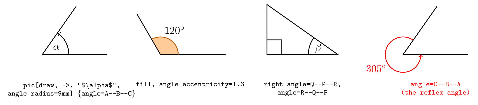
\usepackage{tikz} \usetikzlibrary{angles, quotes}\begin{tikzpicture}[code/.style={font=\ttfamily\scriptsize, align=center, anchor=north}]
% an arc with a label, counter-clockwise from BA to BC
\coordinate (A) at (2.2,0); \coordinate (B) at (0,0); \coordinate (C) at (55:2);
\draw[thick] (A) -- (B) -- (C)
pic[draw, ->, "$\alpha$", angle radius=9mm] {angle=A--B--C};
\node[code] at (1,-0.8) {pic[draw, ->, "\$\textbackslash alpha\$",\\angle radius=9mm] \{angle=A--B--C\}};
% a filled wedge with the label outside it
\coordinate (D) at (6.2,0); \coordinate (E) at (4,0); \coordinate (F) at ([shift=(120:1.6)]E);
\draw[thick] (D) -- (E) -- (F)
pic[fill=orange!40, draw=orange!70!black, "$120^\circ$", angle radius=6mm,
angle eccentricity=1.6] {angle=D--E--F};
\node[code] at (5,-0.8) {fill, angle eccentricity=1.6};
% a right angle, and another angle of the triangle
\coordinate (P) at (7.6,0); \coordinate (Q) at (10,0); \coordinate (R) at (7.6,1.7);
\draw[thick] (P) -- (Q) -- (R) -- cycle
pic[draw] {right angle=Q--P--R}
pic[draw, "$\beta$", angle radius=10mm, angle eccentricity=0.7] {angle=R--Q--P};
\node[code] at (8.8,-0.8) {right angle=Q--P--R,\\angle=R--Q--P};
% the order of the points matters: C--B--A is the outside angle
\coordinate (A2) at (14.4,0); \coordinate (B2) at (12.2,0); \coordinate (C2) at ([shift=(55:2)]B2);
\draw[thick] (A2) -- (B2) -- (C2)
pic[draw, red, ->, "$305^\circ$", angle radius=6mm, angle eccentricity=1.7] {angle=C2--B2--A2};
\node[code, red] at (13.3,-0.8) {angle=C--B--A\\(the reflex angle)};
\end{tikzpicture}Full document
\documentclass[border=4pt]{standalone}
\usepackage{tikz}
\usetikzlibrary{angles, quotes}
\begin{document}
\begin{tikzpicture}[code/.style={font=\ttfamily\scriptsize, align=center, anchor=north}]
  % an arc with a label, counter-clockwise from BA to BC
  \coordinate (A) at (2.2,0); \coordinate (B) at (0,0); \coordinate (C) at (55:2);
  \draw[thick] (A) -- (B) -- (C)
    pic[draw, ->, "$\alpha$", angle radius=9mm] {angle=A--B--C};
  \node[code] at (1,-0.8) {pic[draw, ->, "\$\textbackslash alpha\$",\\angle radius=9mm] \{angle=A--B--C\}};

  % a filled wedge with the label outside it
  \coordinate (D) at (6.2,0); \coordinate (E) at (4,0); \coordinate (F) at ([shift=(120:1.6)]E);
  \draw[thick] (D) -- (E) -- (F)
    pic[fill=orange!40, draw=orange!70!black, "$120^\circ$", angle radius=6mm,
        angle eccentricity=1.6] {angle=D--E--F};
  \node[code] at (5,-0.8) {fill, angle eccentricity=1.6};

  % a right angle, and another angle of the triangle
  \coordinate (P) at (7.6,0); \coordinate (Q) at (10,0); \coordinate (R) at (7.6,1.7);
  \draw[thick] (P) -- (Q) -- (R) -- cycle
    pic[draw] {right angle=Q--P--R}
    pic[draw, "$\beta$", angle radius=10mm, angle eccentricity=0.7] {angle=R--Q--P};
  \node[code] at (8.8,-0.8) {right angle=Q--P--R,\\angle=R--Q--P};

  % the order of the points matters: C--B--A is the outside angle
  \coordinate (A2) at (14.4,0); \coordinate (B2) at (12.2,0); \coordinate (C2) at ([shift=(55:2)]B2);
  \draw[thick] (A2) -- (B2) -- (C2)
    pic[draw, red, ->, "$305^\circ$", angle radius=6mm, angle eccentricity=1.7] {angle=C2--B2--A2};
  \node[code, red] at (13.3,-0.8) {angle=C--B--A\\(the reflex angle)};
\end{tikzpicture}
\end{document}Common errors and how to fix them
| LaTeX says (or you see) | Cause and fix |
|---|---|
| Package tikz Error: You cannot mix dimensions and dimensionless values in an arc. | One radius has a unit and the other does not, as in x radius=1cm, y radius=0.5. Give both with units (1cm and 5mm) or both without. |
| Package pgfkeys Error: I do not know the key '/tikz/1cm' and I am going to ignore it. Perhaps you misspelled it. | circle[1cm] puts the radius in brackets without a key. Write circle[radius=1cm], or the old form circle (1cm). |
| Missing number, treated as zero. | In the old ellipse syntax the two radii are separated by “and”, not a comma: ellipse (2 and 1), or better ellipse[x radius=2, y radius=1]. |
| Package pgfkeys Error: I do not know the key '/tikz/pics/angle', to which you passed 'A--B--C', and I am going to ignore it. Perhaps you misspelled it. | The angle and right angle pics are in a library: add \usetikzlibrary{angles}. |
| Missing \endcsname inserted. | A quoted label such as pic["$\alpha$", draw] {angle=A--B--C} was used without the quotes library. Add \usetikzlibrary{quotes} (next to angles). |
| Package pgfkeys Error: I do not know the key '/tikz/pics/0)--(0' and I am going to ignore it. Perhaps you misspelled it. | The angle pic was given direct coordinates, angle=(1,0)--(0,0)--(0,1). It only accepts names: define \coordinate (A) at (1,0); and so on, or add coordinate (A) after the points of the path, then write angle=A--B--C. |
| Package tikz Error: You need to say \usetikzlibrary{calc} for coordinate calculation. | Coordinates like ($(A)-(C)$), used to compute the angles of an arc between two points, need \usetikzlibrary{calc}. For a simple offset, ([shift=(30:1)]C) works without it. |
| The circle or arc is not drawn at all (no error) | No radius was given. x radius and y radius start at 0pt, so circle and arc without radius, x radius or y radius draw nothing. Add radius=… to the operation or to the picture options. |
| The arc is in the wrong place (no error) | The arc starts at the current point, which is not the centre. Move to the start point first: (C) ++(start angle:radius) arc[start angle=…, end angle=…, radius=…]. |
Frequently asked questions
How do I draw a circle in TikZ?
Write \draw (0,0) circle[radius=1]; for a circle of radius 1 cm around (0,0), or \fill / \filldraw for a filled one. The older \draw (0,0) circle (1); is equivalent. For a circle with text inside, use \node[draw, circle, minimum size=2cm] {text};.
How do I draw an arc in TikZ?
Start at the point where the arc begins and add arc with start angle, end angle and radius: \draw (1,0) arc[start angle=0, end angle=90, radius=1]; draws a quarter circle around (0,0). The old form is \draw (1,0) arc (0:90:1);. Angles are counter-clockwise from the x axis.
How do I draw an arc with a given centre in TikZ?
Move from the centre to the start of the arc with a polar step and then draw the arc with the same angle and radius: \draw (C) ++(30:2) arc[start angle=30, end angle=120, radius=2];. The point ([shift=(30:2)]C) does the same in one coordinate.
How do I draw a half circle in TikZ?
Draw an arc of 180 degrees: \draw (1,0) arc[start angle=0, end angle=180, radius=1]; for the upper half of a circle around (0,0). Add -- cycle to close it along the diameter, for example to fill it. The semicircle node shape from shapes.geometric is a half circle around text.
How do I draw an ellipse in TikZ?
\draw (0,0) ellipse[x radius=2, y radius=1]; or the old \draw (0,0) ellipse (2 and 1);. Add rotate=30 inside the brackets to tilt it. The ellipse node shape (shapes.geometric) fits an ellipse around text.
How do I mark an angle in TikZ?
Load \usetikzlibrary{angles, quotes}, name the points as coordinates, and add pic[draw, "$\alpha$"] {angle=A--B--C} to the path; angle radius sets the size and angle eccentricity the label distance. The angle is measured counter-clockwise from BA to BC, so swap A and C if you get the outer angle. right angle=A--B--C draws a right-angle square.
References
- PGF/TikZ manual, §14.6 The Circle and Ellipse Operationstikz.dev
- PGF/TikZ manual, §14.7 The Arc Operationtikz.dev
- PGF/TikZ manual, §14.15 The Let Operation (atan2, veclen)tikz.dev
- PGF/TikZ manual, §13.4.1 Specifying Relative Coordinates (++ and polar steps)tikz.dev
- PGF/TikZ manual, §13.5 Coordinate Calculations (calc library)tikz.dev
- PGF/TikZ manual, §41 Angle Librarytikz.dev
- PGF/TikZ manual, §17.10.4 The Quotes Syntaxtikz.dev
- PGF/TikZ manual, §71.3 Geometric Shapes (ellipse, semicircle, circular sector)tikz.dev
- pgf package (TikZ) on CTAN, with the full manual as PDFctan.org
The facts on this page were checked against these sources, and every picture is the code with it typeset with TeX Live 2026. Code on this page: CC0 1.0, copy it freely.
Try the code in your browserEvery snippet on this page opens in the free TikZ editor: it is typeset with TeX Live as you type, with errors pointed at their line.
Open the TikZ editor