TikZ shapes: triangles, stars, clouds, cylinders, crosses and braces
Quick answer
\usetikzlibrary{shapes.geometric} for regular polygon (triangle, hexagon …), star, diamond, ellipse and cylinder, shapes.symbols for cloud, shapes.misc for cross out and rounded rectangle, then write \node[draw, star, star points=6] {};. Curly braces are a decoration: \draw[decorate, decoration={brace, amplitude=6pt}] (0,0) -- (3,0); with decorations.pathreplacing. Save a look you reuse with \tikzset{mystyle/.style={…}}.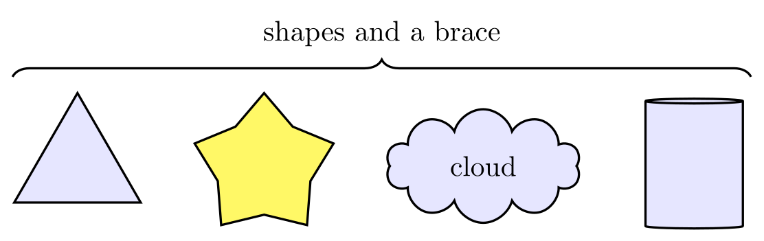
\usepackage{tikz} \usetikzlibrary{shapes.geometric, shapes.symbols} \usetikzlibrary{decorations.pathreplacing}\begin{tikzpicture}[s/.style={draw, thick, fill=blue!10}]
\node[s, regular polygon, regular polygon sides=3, minimum size=1.8cm] at (0,0) {};
\node[s, star, minimum size=1.8cm, fill=yellow!60] at (2.3,0) {};
\node[s, cloud, aspect=1.8, minimum width=2.4cm, minimum height=1.4cm] at (5,0) {cloud};
\node[s, cylinder, shape border rotate=90, aspect=0.25,
minimum height=1.6cm, minimum width=1.2cm] at (7.6,0) {};
\draw[decorate, decoration={brace, amplitude=6pt}, thick] (-0.8,1.1) -- (8.3,1.1)
node[midway, above=7pt] {shapes and a brace};
\end{tikzpicture}Full document
\documentclass[border=4pt]{standalone}
\usepackage{tikz}
\usetikzlibrary{shapes.geometric, shapes.symbols}
\usetikzlibrary{decorations.pathreplacing}
\begin{document}
\begin{tikzpicture}[s/.style={draw, thick, fill=blue!10}]
  \node[s, regular polygon, regular polygon sides=3, minimum size=1.8cm] at (0,0) {};
  \node[s, star, minimum size=1.8cm, fill=yellow!60] at (2.3,0) {};
  \node[s, cloud, aspect=1.8, minimum width=2.4cm, minimum height=1.4cm] at (5,0) {cloud};
  \node[s, cylinder, shape border rotate=90, aspect=0.25,
        minimum height=1.6cm, minimum width=1.2cm] at (7.6,0) {};
  \draw[decorate, decoration={brace, amplitude=6pt}, thick] (-0.8,1.1) -- (8.3,1.1)
    node[midway, above=7pt] {shapes and a brace};
\end{tikzpicture}
\end{document}Contents
The shape libraries and what is in them
A shape is the outline TikZ puts around a node’s text. rectangle, circle and coordinate are built in; all others come from the shape libraries, and the shape name is then used as a node option (\node[draw, cloud] {…};). The libraries, as the manual groups them in §71:
| Library | Shapes |
|---|---|
shapes.geometric | diamond, ellipse, trapezium, semicircle, regular polygon, star, isosceles triangle, kite, dart, circular sector, cylinder |
shapes.symbols | correct forbidden sign, forbidden sign, magnifying glass, cloud, starburst, signal, tape, magnetic tape |
shapes.misc | cross out, strike out, rounded rectangle, chamfered rectangle |
shapes.arrows | single arrow, double arrow, arrow box |
shapes.multipart | circle split, circle solidus, ellipse split, diamond split, rectangle split |
shapes.callouts | rectangle callout, ellipse callout, cloud callout |
\usetikzlibrary{shapes} loads all of them, but the manual says it is “provided for compatibility only”; load the ones you use. Every shape fits itself around the text plus inner sep; minimum size, minimum width and minimum height enlarge it, and for some shapes they mean something particular (the circumcircle of a polygon or star, the length of a cylinder), as described below. Many shapes also take shape border rotate, which turns the outline but not the text; for shapes not built from an incircle it is rounded to a multiple of 90°.
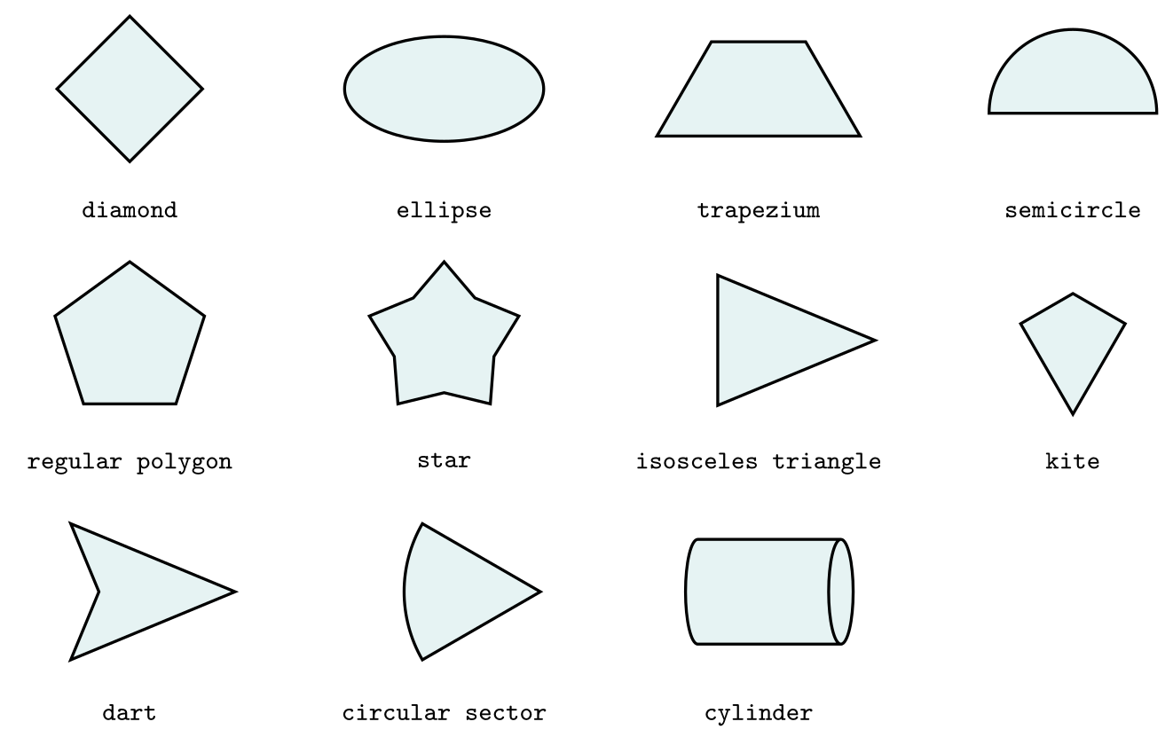
\usepackage{tikz} \usetikzlibrary{shapes.geometric}\begin{tikzpicture}[s/.style={draw, thick, fill=teal!10},
name/.style={font=\ttfamily\scriptsize, anchor=north}]
\node[s, diamond, minimum size=1.4cm] at (0,0) {};
\node[s, ellipse, minimum width=1.9cm, minimum height=1cm] at (3,0) {};
\node[s, trapezium, minimum width=1.6cm, minimum height=0.9cm] at (6,0) {};
\node[s, semicircle, minimum size=0.8cm] at (9,0.1) {};
\node[s, regular polygon, regular polygon sides=5, minimum size=1.5cm] at (0,-2.4) {};
\node[s, star, minimum size=1.5cm] at (3,-2.4) {};
\node[s, isosceles triangle, minimum height=1.5cm] at (6,-2.4) {};
\node[s, kite, minimum size=1cm] at (9,-2.3) {};
\node[s, dart, minimum size=1.3cm] at (0,-4.8) {};
\node[s, circular sector, minimum size=1.3cm] at (3,-4.8) {};
\node[s, cylinder, minimum width=1cm, minimum height=1.6cm] at (6,-4.8) {};
\foreach \n/\x/\y in {diamond/0/0, ellipse/3/0, trapezium/6/0, semicircle/9/0,
regular polygon/0/-2.4, star/3/-2.4, isosceles triangle/6/-2.4, kite/9/-2.4,
dart/0/-4.8, circular sector/3/-4.8, cylinder/6/-4.8}
\node[name] at (\x,\y-0.95) {\n};
\end{tikzpicture}Full document
\documentclass[border=4pt]{standalone}
\usepackage{tikz}
\usetikzlibrary{shapes.geometric}
\begin{document}
\begin{tikzpicture}[s/.style={draw, thick, fill=teal!10},
                    name/.style={font=\ttfamily\scriptsize, anchor=north}]
  \node[s, diamond, minimum size=1.4cm]                     at (0,0)    {};
  \node[s, ellipse, minimum width=1.9cm, minimum height=1cm] at (3,0)    {};
  \node[s, trapezium, minimum width=1.6cm, minimum height=0.9cm] at (6,0) {};
  \node[s, semicircle, minimum size=0.8cm]                  at (9,0.1)  {};
  \node[s, regular polygon, regular polygon sides=5, minimum size=1.5cm] at (0,-2.4) {};
  \node[s, star, minimum size=1.5cm]                        at (3,-2.4) {};
  \node[s, isosceles triangle, minimum height=1.5cm]        at (6,-2.4) {};
  \node[s, kite, minimum size=1cm]                          at (9,-2.3) {};
  \node[s, dart, minimum size=1.3cm]                        at (0,-4.8) {};
  \node[s, circular sector, minimum size=1.3cm]             at (3,-4.8) {};
  \node[s, cylinder, minimum width=1cm, minimum height=1.6cm] at (6,-4.8) {};
  \foreach \n/\x/\y in {diamond/0/0, ellipse/3/0, trapezium/6/0, semicircle/9/0,
      regular polygon/0/-2.4, star/3/-2.4, isosceles triangle/6/-2.4, kite/9/-2.4,
      dart/0/-4.8, circular sector/3/-4.8, cylinder/6/-4.8}
    \node[name] at (\x,\y-0.95) {\n};
\end{tikzpicture}
\end{document}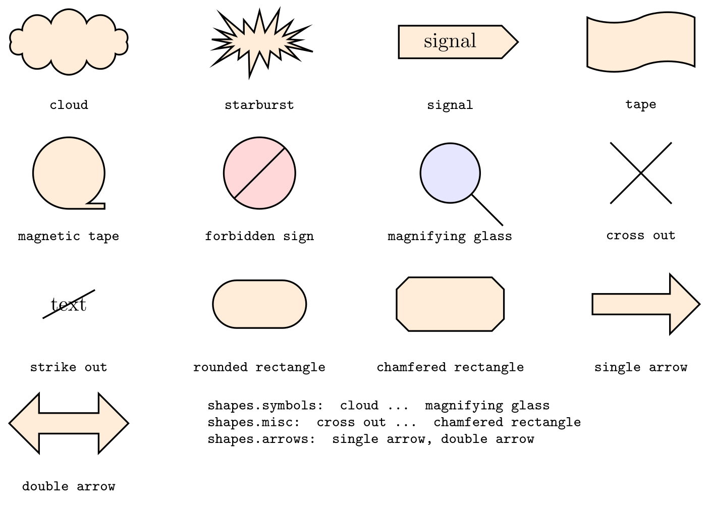
\usepackage{tikz} \usetikzlibrary{shapes.symbols, shapes.misc, shapes.arrows}\begin{tikzpicture}[s/.style={draw, thick, fill=orange!15},
name/.style={font=\ttfamily\scriptsize, anchor=north}]
\node[s, cloud, minimum width=2cm, minimum height=1.1cm] at (0,0) {};
\node[s, starburst, minimum width=2cm, minimum height=1.2cm] at (3.2,0) {};
\node[s, signal, signal to=east, minimum width=2cm] at (6.4,0) {signal};
\node[s, tape, minimum width=1.8cm, minimum height=1cm] at (9.6,0) {};
\node[s, magnetic tape, minimum size=1.2cm] at (0,-2.2) {};
\node[s, forbidden sign, minimum size=1.2cm, fill=red!15] at (3.2,-2.2) {};
\node[s, magnifying glass, minimum size=1cm, fill=blue!10] at (6.4,-2.2) {};
\node[s, cross out, fill=none, minimum size=1cm] at (9.6,-2.2) {};
\node[s, strike out, fill=none] at (0,-4.4) {text};
\node[s, rounded rectangle, minimum width=1.8cm, minimum height=0.8cm] at (3.2,-4.4) {};
\node[s, chamfered rectangle, minimum width=1.8cm, minimum height=0.9cm] at (6.4,-4.4) {};
\node[s, single arrow, minimum width=1cm, minimum height=1.8cm] at (9.6,-4.4) {};
\node[s, double arrow, minimum width=1cm, minimum height=2cm] at (0,-6.4) {};
\foreach \n/\x/\y in {cloud/0/0, starburst/3.2/0, signal/6.4/0, tape/9.6/0,
magnetic tape/0/-2.2, forbidden sign/3.2/-2.2, magnifying glass/6.4/-2.2,
cross out/9.6/-2.2, strike out/0/-4.4, rounded rectangle/3.2/-4.4,
chamfered rectangle/6.4/-4.4, single arrow/9.6/-4.4, double arrow/0/-6.4}
\node[name] at (\x,\y-0.85) {\n};
\node[font=\ttfamily\scriptsize, align=left, anchor=west] at (2.2,-6.4)
{shapes.symbols: cloud ... magnifying glass\\shapes.misc: cross out ... chamfered rectangle\\shapes.arrows: single arrow, double arrow};
\end{tikzpicture}Full document
\documentclass[border=4pt]{standalone}
\usepackage{tikz}
\usetikzlibrary{shapes.symbols, shapes.misc, shapes.arrows}
\begin{document}
\begin{tikzpicture}[s/.style={draw, thick, fill=orange!15},
                    name/.style={font=\ttfamily\scriptsize, anchor=north}]
  \node[s, cloud, minimum width=2cm, minimum height=1.1cm]       at (0,0)    {};
  \node[s, starburst, minimum width=2cm, minimum height=1.2cm]   at (3.2,0)  {};
  \node[s, signal, signal to=east, minimum width=2cm]            at (6.4,0)  {signal};
  \node[s, tape, minimum width=1.8cm, minimum height=1cm]        at (9.6,0)  {};
  \node[s, magnetic tape, minimum size=1.2cm]                    at (0,-2.2) {};
  \node[s, forbidden sign, minimum size=1.2cm, fill=red!15]      at (3.2,-2.2) {};
  \node[s, magnifying glass, minimum size=1cm, fill=blue!10]     at (6.4,-2.2) {};
  \node[s, cross out, fill=none, minimum size=1cm]               at (9.6,-2.2) {};
  \node[s, strike out, fill=none]                                at (0,-4.4) {text};
  \node[s, rounded rectangle, minimum width=1.8cm, minimum height=0.8cm] at (3.2,-4.4) {};
  \node[s, chamfered rectangle, minimum width=1.8cm, minimum height=0.9cm] at (6.4,-4.4) {};
  \node[s, single arrow, minimum width=1cm, minimum height=1.8cm] at (9.6,-4.4) {};
  \node[s, double arrow, minimum width=1cm, minimum height=2cm]  at (0,-6.4) {};
  \foreach \n/\x/\y in {cloud/0/0, starburst/3.2/0, signal/6.4/0, tape/9.6/0,
      magnetic tape/0/-2.2, forbidden sign/3.2/-2.2, magnifying glass/6.4/-2.2,
      cross out/9.6/-2.2, strike out/0/-4.4, rounded rectangle/3.2/-4.4,
      chamfered rectangle/6.4/-4.4, single arrow/9.6/-4.4, double arrow/0/-6.4}
    \node[name] at (\x,\y-0.85) {\n};
  \node[font=\ttfamily\scriptsize, align=left, anchor=west] at (2.2,-6.4)
    {shapes.symbols: cloud ... magnifying glass\\shapes.misc: cross out ... chamfered rectangle\\shapes.arrows: single arrow, double arrow};
\end{tikzpicture}
\end{document}Triangles
There are three ways to draw a triangle, depending on what you need:
- Equilateral:
regular polygon, regular polygon sides=3(shapes.geometric). The polygon always has a side at the bottom, andminimum sizeis the diameter of the circle through its corners, sominimum size=2cmgives a triangle with sides of about 1.73 cm. Its anchors includecorner 1(the top) tocorner 3andside 1toside 3. The same shape makes pentagons and hexagons withregular polygon sides=5or6. - Isosceles:
isosceles trianglepoints to the right;shape border rotate=90points it up, andisosceles triangle apex anglesets the tip angle. The manual gives 30 as its initial value, but pgf 3.1.12 uses 45, which is what the default triangle below has. Its anchors areapex,left corner,right cornerand the sides. Withisosceles triangle stretches, minimum width and height can be set independently instead of keeping the apex angle. - Any triangle: a path through three points, closed with
-- cycle:\draw (0,0) -- (3,0) -- (0,2) -- cycle;. Use this for geometry with given vertices; name the points withcoordinate (P)to label them or to mark angles (see circles and arcs).
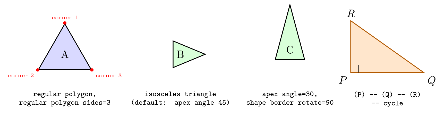
\usepackage{tikz} \usetikzlibrary{shapes.geometric}\begin{tikzpicture}[code/.style={font=\ttfamily\scriptsize, align=center, anchor=north}]
% equilateral: a regular polygon with 3 sides (minimum size = circumcircle diameter)
\node[regular polygon, regular polygon sides=3, minimum size=2cm,
draw, thick, fill=blue!15] (t) at (0,0) {A};
\foreach \c/\p in {1/above, 2/below left, 3/below right}
\fill[red] (t.corner \c) circle[radius=1.5pt] node[\p, font=\tiny] {corner \c};
\node[code] at (0,-1.1) {regular polygon,\\regular polygon sides=3};
% isosceles triangle: the apex points along shape border rotate
\node[isosceles triangle, draw, thick, fill=green!15] at (3.8,0) {B};
\node[code] at (3.8,-1.1) {isosceles triangle\\(default: apex angle 45)};
\node[isosceles triangle, isosceles triangle apex angle=30, shape border rotate=90,
minimum height=1.8cm, draw, thick, fill=green!15] at (7.4,0.15) {C};
\node[code] at (7.4,-1.1) {apex angle=30,\\shape border rotate=90};
% any triangle: three points and -- cycle
\filldraw[fill=orange!20, draw=orange!70!black, thick] (9.4,-0.6) coordinate (P)
-- (11.8,-0.6) coordinate (Q) -- (9.4,1.1) coordinate (R) -- cycle;
\draw (9.4,-0.35) -| (9.65,-0.6);
\node[below left] at (P) {$P$}; \node[below right] at (Q) {$Q$}; \node[above] at (R) {$R$};
\node[code] at (10.6,-1.1) {(P) -- (Q) -- (R)\\-- cycle};
\end{tikzpicture}Full document
\documentclass[border=4pt]{standalone}
\usepackage{tikz}
\usetikzlibrary{shapes.geometric}
\begin{document}
\begin{tikzpicture}[code/.style={font=\ttfamily\scriptsize, align=center, anchor=north}]
  % equilateral: a regular polygon with 3 sides (minimum size = circumcircle diameter)
  \node[regular polygon, regular polygon sides=3, minimum size=2cm,
        draw, thick, fill=blue!15] (t) at (0,0) {A};
  \foreach \c/\p in {1/above, 2/below left, 3/below right}
    \fill[red] (t.corner \c) circle[radius=1.5pt] node[\p, font=\tiny] {corner \c};
  \node[code] at (0,-1.1) {regular polygon,\\regular polygon sides=3};

  % isosceles triangle: the apex points along shape border rotate
  \node[isosceles triangle, draw, thick, fill=green!15] at (3.8,0) {B};
  \node[code] at (3.8,-1.1) {isosceles triangle\\(default: apex angle 45)};
  \node[isosceles triangle, isosceles triangle apex angle=30, shape border rotate=90,
        minimum height=1.8cm, draw, thick, fill=green!15] at (7.4,0.15) {C};
  \node[code] at (7.4,-1.1) {apex angle=30,\\shape border rotate=90};

  % any triangle: three points and -- cycle
  \filldraw[fill=orange!20, draw=orange!70!black, thick] (9.4,-0.6) coordinate (P)
    -- (11.8,-0.6) coordinate (Q) -- (9.4,1.1) coordinate (R) -- cycle;
  \draw (9.4,-0.35) -| (9.65,-0.6);
  \node[below left] at (P) {$P$}; \node[below right] at (Q) {$Q$}; \node[above] at (R) {$R$};
  \node[code] at (10.6,-1.1) {(P) -- (Q) -- (R)\\-- cycle};
\end{tikzpicture}
\end{document}Stars
star (shapes.geometric) draws a star with its first point up. star points (initially 5) sets the number of points. The depth of the points is set by one of two keys: star point ratio (initially 1.5), the outer radius divided by the inner one, or star point height (initially .5cm), the length of the points. Whichever of the two you set last is used, and by default it is the ratio, a detail the manual leaves out. A minimum size is the diameter of the circle through the outer points.
The star is built around the circle that encloses the text, so text makes it grow quickly; for a star with a label, put the text next to it with label=. rotate=18 turns the whole node; shape border rotate turns only the outline.
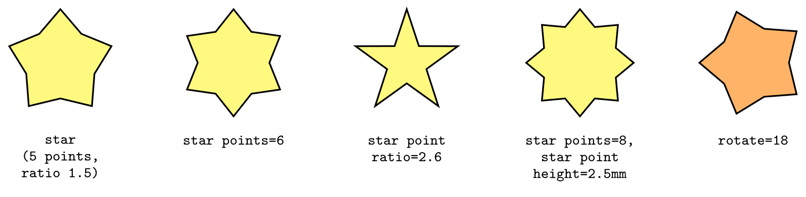
\usepackage{tikz} \usetikzlibrary{shapes.geometric}\begin{tikzpicture}[s/.style={star, draw, thick, fill=yellow!50, minimum size=1.8cm},
code/.style={font=\ttfamily\scriptsize, align=center, anchor=north}]
\node[s] at (0,0) {};
\node[code] at (0,-1.1) {star\\(5 points,\\ratio 1.5)};
\node[s, star points=6] at (2.9,0) {};
\node[code] at (2.9,-1.1) {star points=6};
\node[s, star point ratio=2.6] at (5.8,0) {};
\node[code] at (5.8,-1.1) {star point\\ratio=2.6};
\node[s, star points=8, star point height=2.5mm] at (8.7,0) {};
\node[code] at (8.7,-1.1) {star points=8,\\star point\\height=2.5mm};
\node[s, fill=orange!60, rotate=18] at (11.6,0) {};
\node[code] at (11.6,-1.1) {rotate=18};
\end{tikzpicture}Full document
\documentclass[border=4pt]{standalone}
\usepackage{tikz}
\usetikzlibrary{shapes.geometric}
\begin{document}
\begin{tikzpicture}[s/.style={star, draw, thick, fill=yellow!50, minimum size=1.8cm},
                    code/.style={font=\ttfamily\scriptsize, align=center, anchor=north}]
  \node[s] at (0,0) {};
  \node[code] at (0,-1.1) {star\\(5 points,\\ratio 1.5)};
  \node[s, star points=6] at (2.9,0) {};
  \node[code] at (2.9,-1.1) {star points=6};
  \node[s, star point ratio=2.6] at (5.8,0) {};
  \node[code] at (5.8,-1.1) {star point\\ratio=2.6};
  \node[s, star points=8, star point height=2.5mm] at (8.7,0) {};
  \node[code] at (8.7,-1.1) {star points=8,\\star point\\height=2.5mm};
  \node[s, fill=orange!60, rotate=18] at (11.6,0) {};
  \node[code] at (11.6,-1.1) {rotate=18};
\end{tikzpicture}
\end{document}Cylinders
cylinder (shapes.geometric) lies on its side by default, with the curved top on the right, which surprises most people; shape border rotate=90 stands it up for the usual database symbol. Whatever the rotation, the manual defines its height as the distance between the curved ends and its width as the distance between the straight sides, so for an upright cylinder minimum height is the visual height. A minimum height stretches only the body; a minimum width also widens the ends.
aspect (initially 1) is the ratio of the radii of the elliptical ends: smaller values flatten them, as the three cylinders on the right show. To colour the top and the body differently, set cylinder uses custom fill with cylinder end fill and cylinder body fill (both initially white) and do not give the node a fill. The anchors include top, bottom, before top, after top and shape center, which, unlike center, includes the drawn top.
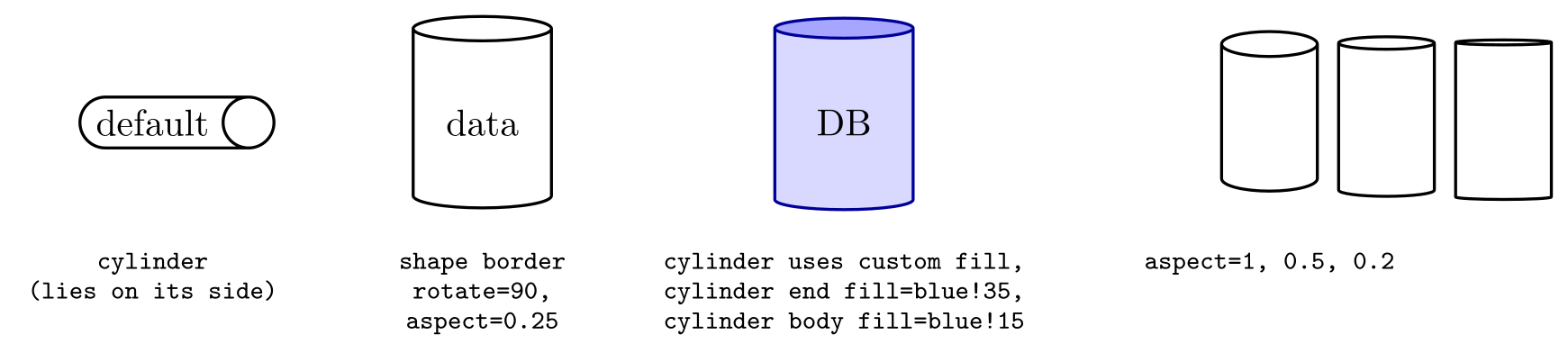
\usepackage{tikz} \usetikzlibrary{shapes.geometric}\begin{tikzpicture}[code/.style={font=\ttfamily\scriptsize, align=center, anchor=north}]
\node[cylinder, draw, thick, minimum height=1.6cm] at (0,0) {default};
\node[code] at (0,-1.1) {cylinder\\(lies on its side)};
\node[cylinder, draw, thick, shape border rotate=90, aspect=0.25,
minimum height=1.8cm, minimum width=1.3cm] at (3.1,0) {data};
\node[code] at (3.1,-1.1) {shape border\\rotate=90,\\aspect=0.25};
\node[cylinder, draw=blue!60!black, thick, shape border rotate=90, aspect=0.25,
minimum height=1.8cm, minimum width=1.3cm, cylinder uses custom fill,
cylinder end fill=blue!35, cylinder body fill=blue!15] at (6.5,0) {DB};
\node[code] at (6.5,-1.1) {cylinder uses custom fill,\\cylinder end fill=blue!35,\\cylinder body fill=blue!15};
\foreach \a [count=\i] in {1, 0.5, 0.2}
\node[cylinder, draw, thick, shape border rotate=90, aspect=\a,
minimum height=1.5cm, minimum width=0.9cm] at (9.4+1.1*\i,0) {};
\node[code] at (10.5,-1.1) {aspect=1, 0.5, 0.2};
\end{tikzpicture}Full document
\documentclass[border=4pt]{standalone}
\usepackage{tikz}
\usetikzlibrary{shapes.geometric}
\begin{document}
\begin{tikzpicture}[code/.style={font=\ttfamily\scriptsize, align=center, anchor=north}]
  \node[cylinder, draw, thick, minimum height=1.6cm] at (0,0) {default};
  \node[code] at (0,-1.1) {cylinder\\(lies on its side)};

  \node[cylinder, draw, thick, shape border rotate=90, aspect=0.25,
        minimum height=1.8cm, minimum width=1.3cm] at (3.1,0) {data};
  \node[code] at (3.1,-1.1) {shape border\\rotate=90,\\aspect=0.25};

  \node[cylinder, draw=blue!60!black, thick, shape border rotate=90, aspect=0.25,
        minimum height=1.8cm, minimum width=1.3cm, cylinder uses custom fill,
        cylinder end fill=blue!35, cylinder body fill=blue!15] at (6.5,0) {DB};
  \node[code] at (6.5,-1.1) {cylinder uses custom fill,\\cylinder end fill=blue!35,\\cylinder body fill=blue!15};

  \foreach \a [count=\i] in {1, 0.5, 0.2}
    \node[cylinder, draw, thick, shape border rotate=90, aspect=\a,
          minimum height=1.5cm, minimum width=0.9cm] at (9.4+1.1*\i,0) {};
  \node[code] at (10.5,-1.1) {aspect=1, 0.5, 0.2};
\end{tikzpicture}
\end{document}Clouds
cloud (shapes.symbols) draws a ring of arcs (puffs) around an ellipse that fits the text. cloud puffs (initially 10) sets how many, and cloud puff arc how much of a circle each puff is. The manual gives 135° as its initial value; pgf 3.1.12 uses 150. Smaller arcs make flatter puffs and, per the manual, better joins with thick lines.
The cloud keeps the aspect ratio (initially 1) of width to height, and with text inside that wins over the minimum sizes: minimum width=2.6cm, minimum height=1.6cm around “Internet” still gave a round cloud. Set an aspect such as 2, or add cloud ignores aspect, as in the third example. The minimum sizes then apply to the ellipse through the middle of the puffs. For a speech or thought bubble with a pointer, the cloud callout shape of shapes.callouts is ready-made (see text boxes); a cloud with two small circles, as below, is the hand-made version.
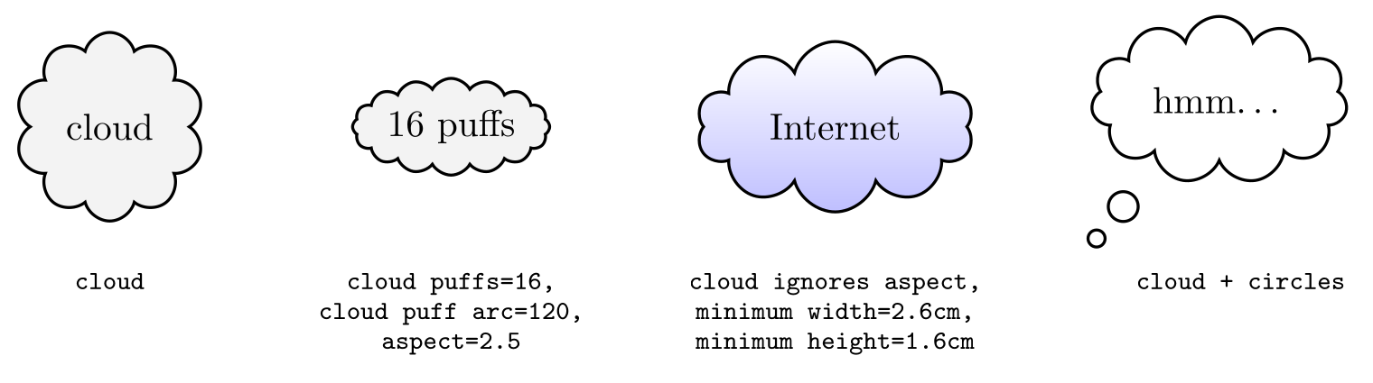
\usepackage{tikz} \usetikzlibrary{shapes.symbols}\begin{tikzpicture}[code/.style={font=\ttfamily\scriptsize, align=center, anchor=north}]
\node[cloud, draw, thick, fill=gray!10] at (0,0) {cloud};
\node[code] at (0,-1.25) {cloud};
\node[cloud, draw, thick, fill=gray!10, cloud puffs=16, cloud puff arc=120,
aspect=2.5, inner sep=1pt] at (3.2,0) {16 puffs};
\node[code] at (3.2,-1.25) {cloud puffs=16,\\cloud puff arc=120,\\aspect=2.5};
\node[cloud, draw, thick, top color=white, bottom color=blue!25, cloud ignores aspect,
minimum width=2.6cm, minimum height=1.6cm] at (6.8,0) {Internet};
\node[code] at (6.8,-1.25) {cloud ignores aspect,\\minimum width=2.6cm,\\minimum height=1.6cm};
% a thought bubble: a cloud and two small circles
\node[cloud, draw, thick, fill=white, cloud puffs=11, aspect=1.8, minimum width=2.4cm,
minimum height=1.3cm] at (10.4,0.25) {hmm\dots};
\draw[thick, fill=white] (9.5,-0.75) circle[radius=0.14] (9.25,-1.05) circle[radius=0.08];
\node[code] at (10.6,-1.25) {cloud + circles};
\end{tikzpicture}Full document
\documentclass[border=4pt]{standalone}
\usepackage{tikz}
\usetikzlibrary{shapes.symbols}
\begin{document}
\begin{tikzpicture}[code/.style={font=\ttfamily\scriptsize, align=center, anchor=north}]
  \node[cloud, draw, thick, fill=gray!10] at (0,0) {cloud};
  \node[code] at (0,-1.25) {cloud};

  \node[cloud, draw, thick, fill=gray!10, cloud puffs=16, cloud puff arc=120,
        aspect=2.5, inner sep=1pt] at (3.2,0) {16 puffs};
  \node[code] at (3.2,-1.25) {cloud puffs=16,\\cloud puff arc=120,\\aspect=2.5};

  \node[cloud, draw, thick, top color=white, bottom color=blue!25, cloud ignores aspect,
        minimum width=2.6cm, minimum height=1.6cm] at (6.8,0) {Internet};
  \node[code] at (6.8,-1.25) {cloud ignores aspect,\\minimum width=2.6cm,\\minimum height=1.6cm};

  % a thought bubble: a cloud and two small circles
  \node[cloud, draw, thick, fill=white, cloud puffs=11, aspect=1.8, minimum width=2.4cm,
        minimum height=1.3cm] at (10.4,0.25) {hmm\dots};
  \draw[thick, fill=white] (9.5,-0.75) circle[radius=0.14] (9.25,-1.05) circle[radius=0.08];
  \node[code] at (10.6,-1.25) {cloud + circles};
\end{tikzpicture}
\end{document}Crosses: cross out, strike out and cross marks
cross out and strike out (shapes.misc) are rectangles whose drawing is two diagonals or one diagonal over the node, used to strike through text; they have all the rectangle’s anchors. Inside a paragraph, \tikz[baseline] \node[cross out, draw, anchor=text] {word}; keeps the word on the line.
For small × marks at points, as on a plot, use an empty cross out node with a fixed size: x mark/.style={cross out, draw, minimum size=6pt, inner sep=0pt} and \node[x mark] at (2,1) {};. Plot marks are another option: \draw plot[mark=x] coordinates {(1,1) (2,0)}; uses the built-in x and + marks (only marks leaves out the line). A plus sign is two short lines from the point, (p) +(-4pt,0) -- +(4pt,0) +(0,-4pt) -- +(0,4pt), and a solid cross is two rectangles in one \fill.
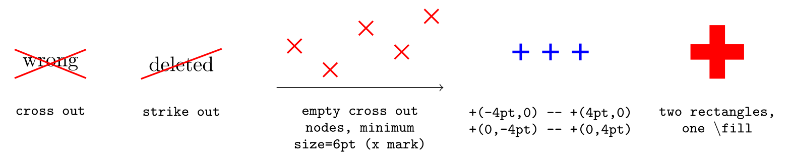
\usepackage{tikz} \usetikzlibrary{shapes.misc}\begin{tikzpicture}[code/.style={font=\ttfamily\scriptsize, align=center, anchor=north},
x mark/.style={cross out, draw=red, thick, minimum size=6pt, inner sep=0pt}]
% cross out and strike out draw over the node
\node[cross out, draw=red, thick] at (0,0) {wrong};
\node[code] at (0,-0.6) {cross out};
\node[strike out, draw=red, thick] at (2.2,0) {deleted};
\node[code] at (2.2,-0.6) {strike out};
% small x marks at points: an empty cross out node of fixed size
\draw[->] (3.8,-0.4) -- (6.6,-0.4);
\foreach \x/\y in {4.1/0.3, 4.7/-0.1, 5.3/0.6, 5.9/0.2, 6.4/0.8}
\node[x mark] at (\x,\y) {};
\node[code] at (5.2,-0.6) {empty cross out\\nodes, minimum\\size=6pt (x mark)};
% plus signs and a filled cross as paths
\foreach \x in {7.9,8.4,8.9}
\draw[very thick, blue] (\x,0.2) +(-4pt,0) -- +(4pt,0) +(0,-4pt) -- +(0,4pt);
\node[code] at (8.4,-0.6) {+(-4pt,0) -- +(4pt,0)\\+(0,-4pt) -- +(0,4pt)};
\fill[red] (11.2,0.2) +(-0.45,-0.13) rectangle +(0.45,0.13)
+(-0.13,-0.45) rectangle +(0.13,0.45);
\node[code] at (11.2,-0.6) {two rectangles,\\one \textbackslash fill};
\end{tikzpicture}Full document
\documentclass[border=4pt]{standalone}
\usepackage{tikz}
\usetikzlibrary{shapes.misc}
\begin{document}
\begin{tikzpicture}[code/.style={font=\ttfamily\scriptsize, align=center, anchor=north},
                    x mark/.style={cross out, draw=red, thick, minimum size=6pt, inner sep=0pt}]
  % cross out and strike out draw over the node
  \node[cross out, draw=red, thick] at (0,0) {wrong};
  \node[code] at (0,-0.6) {cross out};
  \node[strike out, draw=red, thick] at (2.2,0) {deleted};
  \node[code] at (2.2,-0.6) {strike out};

  % small x marks at points: an empty cross out node of fixed size
  \draw[->] (3.8,-0.4) -- (6.6,-0.4);
  \foreach \x/\y in {4.1/0.3, 4.7/-0.1, 5.3/0.6, 5.9/0.2, 6.4/0.8}
    \node[x mark] at (\x,\y) {};
  \node[code] at (5.2,-0.6) {empty cross out\\nodes, minimum\\size=6pt (x mark)};

  % plus signs and a filled cross as paths
  \foreach \x in {7.9,8.4,8.9}
    \draw[very thick, blue] (\x,0.2) +(-4pt,0) -- +(4pt,0) +(0,-4pt) -- +(0,4pt);
  \node[code] at (8.4,-0.6) {+(-4pt,0) -- +(4pt,0)\\+(0,-4pt) -- +(0,4pt)};
  \fill[red] (11.2,0.2) +(-0.45,-0.13) rectangle +(0.45,0.13)
                        +(-0.13,-0.45) rectangle +(0.13,0.45);
  \node[code] at (11.2,-0.6) {two rectangles,\\one \textbackslash fill};
\end{tikzpicture}
\end{document}Curly braces: the brace decoration
A curly brace is drawn by decorating a straight line: load \usetikzlibrary{decorations.pathreplacing} and write \draw[decorate, decoration={brace, amplitude=6pt}] (0,0) -- (4,0);. The line is replaced by a brace from its start to its end. The decoration keys:
amplitude(initially 2.5pt): how far the brace rises above the line; 5–10pt looks right for most figures.mirror: flip the brace to the other side. A brace bulges to the left of the drawing direction, so from left to right it opens downwards and points up; drawing from right to left, or addingmirror, points it down.raise(initially 0pt): move it away from the line, to leave a gap to the thing it groups.aspect(initially 0.5): where the tip is, as a fraction of the length.
For a label, put a node on the path with midway and an offset larger than the amplitude: node[midway, above=8pt] {text}. To group nodes, draw between their anchors, for example from (a.north east) to (c.south east) with raise=3pt for a brace on the right of a column. The brace only makes sense on a straight line. For a brace next to a matrix or an equation, the matrix library’s left delimiter=\{ uses the font’s brace instead.
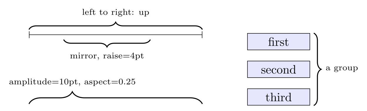
\usepackage{tikz} \usetikzlibrary{decorations.pathreplacing}\begin{tikzpicture}[brace/.style={decorate, decoration={brace, amplitude=#1}, thick},
brace/.default=6pt, note/.style={font=\scriptsize}]
% a brace bulges to the left of the path direction: left to right = up
\draw[|-|] (0,0) -- (5,0);
\draw[brace] (0,0.15) -- (5,0.15) node[midway, above=7pt, note] {left to right: up};
% mirror flips it; raise moves it off the path
\draw[brace, decoration={mirror, raise=4pt}] (1,0) -- (3.5,0)
node[midway, below=11pt, note] {mirror, raise=4pt};
% aspect moves the tip; amplitude sets its height
\draw[brace=10pt, decoration={aspect=0.25}] (0,-2) -- (5,-2)
node[pos=0.25, above=11pt, note] {amplitude=10pt, aspect=0.25};
% a vertical brace next to a group of nodes, drawn top to bottom
\foreach \t [count=\i] in {first, second, third}
\node[draw, fill=blue!10, minimum width=1.8cm] (n\i) at (7.2,0.6-0.8*\i) {\t};
\draw[brace, decoration={raise=3pt}] (n1.north east) -- (n3.south east)
node[midway, right=9pt, note] {a group};
\end{tikzpicture}Full document
\documentclass[border=4pt]{standalone}
\usepackage{tikz}
\usetikzlibrary{decorations.pathreplacing}
\begin{document}
\begin{tikzpicture}[brace/.style={decorate, decoration={brace, amplitude=#1}, thick},
                    brace/.default=6pt, note/.style={font=\scriptsize}]
  % a brace bulges to the left of the path direction: left to right = up
  \draw[|-|] (0,0) -- (5,0);
  \draw[brace] (0,0.15) -- (5,0.15) node[midway, above=7pt, note] {left to right: up};
  % mirror flips it; raise moves it off the path
  \draw[brace, decoration={mirror, raise=4pt}] (1,0) -- (3.5,0)
    node[midway, below=11pt, note] {mirror, raise=4pt};
  % aspect moves the tip; amplitude sets its height
  \draw[brace=10pt, decoration={aspect=0.25}] (0,-2) -- (5,-2)
    node[pos=0.25, above=11pt, note] {amplitude=10pt, aspect=0.25};

  % a vertical brace next to a group of nodes, drawn top to bottom
  \foreach \t [count=\i] in {first, second, third}
    \node[draw, fill=blue!10, minimum width=1.8cm] (n\i) at (7.2,0.6-0.8*\i) {\t};
  \draw[brace, decoration={raise=3pt}] (n1.north east) -- (n3.south east)
    node[midway, right=9pt, note] {a group};
\end{tikzpicture}
\end{document}Calligraphic braces
The brace decoration has a constant line width. For a brace that tapers like a hand-drawn one, use calligraphic brace from the calligraphy library. It is not part of PGF: it comes with the spath3 package (included in TeX Live), and it defines its decorations only if a decorations library was loaded before it, so load them in this order: \usetikzlibrary{decorations.pathreplacing, calligraphy}. With the libraries the other way round, LaTeX reports that it does not know the key /pgf/decoration/calligraphic brace.
amplitude, mirror and raise work as for the normal brace, and the line width sets the thickest part (ultra thick or line width=1.5pt look best). Two things differ: the brace is filled, not stroked, so a colour such as red on the path is ignored and you colour it with pen colour=red; and the library also offers calligraphic straight parenthesis and calligraphic curved parenthesis.
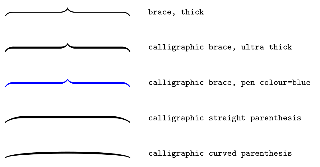
\usepackage{tikz} \usetikzlibrary{decorations.pathreplacing, calligraphy}\begin{tikzpicture}[code/.style={font=\ttfamily\scriptsize, anchor=west}]
\draw[decorate, decoration={brace, amplitude=6pt}, thick] (0,0) -- (3.5,0);
\node[code] at (3.9,0.1) {brace, thick};
\draw[decorate, decoration={calligraphic brace, amplitude=6pt}, ultra thick] (0,-1) -- (3.5,-1);
\node[code] at (3.9,-0.9) {calligraphic brace, ultra thick};
\draw[decorate, decoration={calligraphic brace, amplitude=6pt}, line width=1.5pt,
pen colour=blue] (0,-2) -- (3.5,-2);
\node[code] at (3.9,-1.9) {calligraphic brace, pen colour=blue};
\draw[decorate, decoration={calligraphic straight parenthesis, amplitude=4pt},
ultra thick] (0,-3) -- (3.5,-3);
\node[code] at (3.9,-2.9) {calligraphic straight parenthesis};
\draw[decorate, decoration={calligraphic curved parenthesis, amplitude=4pt},
ultra thick] (0,-4) -- (3.5,-4);
\node[code] at (3.9,-3.9) {calligraphic curved parenthesis};
\end{tikzpicture}Full document
\documentclass[border=4pt]{standalone}
\usepackage{tikz}
\usetikzlibrary{decorations.pathreplacing, calligraphy}
\begin{document}
\begin{tikzpicture}[code/.style={font=\ttfamily\scriptsize, anchor=west}]
  \draw[decorate, decoration={brace, amplitude=6pt}, thick] (0,0) -- (3.5,0);
  \node[code] at (3.9,0.1) {brace, thick};
  \draw[decorate, decoration={calligraphic brace, amplitude=6pt}, ultra thick] (0,-1) -- (3.5,-1);
  \node[code] at (3.9,-0.9) {calligraphic brace, ultra thick};
  \draw[decorate, decoration={calligraphic brace, amplitude=6pt}, line width=1.5pt,
        pen colour=blue] (0,-2) -- (3.5,-2);
  \node[code] at (3.9,-1.9) {calligraphic brace, pen colour=blue};
  \draw[decorate, decoration={calligraphic straight parenthesis, amplitude=4pt},
        ultra thick] (0,-3) -- (3.5,-3);
  \node[code] at (3.9,-2.9) {calligraphic straight parenthesis};
  \draw[decorate, decoration={calligraphic curved parenthesis, amplitude=4pt},
        ultra thick] (0,-4) -- (3.5,-4);
  \node[code] at (3.9,-3.9) {calligraphic curved parenthesis};
\end{tikzpicture}
\end{document}Custom styles with \tikzset (and why not \tikzstyle)
A style is a named list of options. Define it with \tikzset{box/.style={draw, thick, rounded corners}} in the preamble to use it in every picture, or in a picture’s or scope’s options to keep it local; then write \node[box] {…};. Styles can do more than abbreviate:
- Parameters:
#1in the definition is the value:box/.style={…, fill=#1!15}and\node[box=green].box/.default=blueis used when no value is given. - Styles using styles:
warn/.style={box=red, font=\bfseries}. - Changing a style:
box/.append style={dashed}adds options, for example to the built-inevery nodeorhelp lines. - Your own shapes: a
picis a small reusable drawing,house/.pic={…}, placed with\pic at (2,0) {house};and scaled with\pic[scale=0.6](§18).
Older code defines styles with \tikzstyle{box}=[draw, thick]. It still works: tikz.code.tex defines it, including \tikzstyle{box}+=[…] for appending and \tikzstyle{tag}[red]=[draw=#1] for a default. But the current manual no longer mentions \tikzstyle anywhere; it documents styles only through \tikzset and /.style (§12.4.2), which is why it is called deprecated. \tikzset uses the same key mechanism as every other option, so it can set many styles and other options at once, and the same definition works in the preamble, in a picture or in a scope. A style defined in one picture’s options is unknown in the next picture: put shared styles in \tikzset.
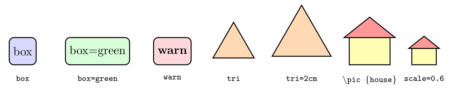
\usepackage{tikz} \usetikzlibrary{shapes.geometric}\tikzset{
box/.style={draw, thick, rounded corners, fill=#1!15, minimum height=8mm},
box/.default=blue,
warn/.style={box=red, font=\bfseries},
tri/.style={regular polygon, regular polygon sides=3, draw, thick,
fill=orange!30, minimum size=#1},
tri/.default=1.4cm,
house/.pic={
\filldraw[fill=yellow!30, thick] (-0.6,0) rectangle (0.6,0.8);
\filldraw[fill=red!40, thick] (-0.75,0.8) -- (0,1.4) -- (0.75,0.8) -- cycle;
},
}
\begin{tikzpicture}[code/.style={font=\ttfamily\scriptsize, anchor=north}]
\node[box] at (0,0) {box}; \node[code] at (0,-0.6) {box};
\node[box=green] at (2.2,0) {box=green}; \node[code] at (2.2,-0.6) {box=green};
\node[warn] at (4.4,0) {warn}; \node[code] at (4.4,-0.6) {warn};
\node[tri] at (6.2,0.15) {}; \node[code] at (6.2,-0.6) {tri};
\node[tri=2cm] at (8.2,0.35) {}; \node[code] at (8.2,-0.6) {tri=2cm};
\pic at (10.2,-0.4) {house}; \node[code] at (10.2,-0.6) {\textbackslash pic \{house\}};
\pic[scale=0.6] at (11.8,-0.4) {house}; \node[code] at (11.8,-0.6) {scale=0.6};
\end{tikzpicture}Full document
\documentclass[border=4pt]{standalone}
\usepackage{tikz}
\usetikzlibrary{shapes.geometric}
\begin{document}
\tikzset{
  box/.style={draw, thick, rounded corners, fill=#1!15, minimum height=8mm},
  box/.default=blue,
  warn/.style={box=red, font=\bfseries},
  tri/.style={regular polygon, regular polygon sides=3, draw, thick,
              fill=orange!30, minimum size=#1},
  tri/.default=1.4cm,
  house/.pic={
    \filldraw[fill=yellow!30, thick] (-0.6,0) rectangle (0.6,0.8);
    \filldraw[fill=red!40, thick] (-0.75,0.8) -- (0,1.4) -- (0.75,0.8) -- cycle;
  },
}
\begin{tikzpicture}[code/.style={font=\ttfamily\scriptsize, anchor=north}]
  \node[box] at (0,0) {box};              \node[code] at (0,-0.6) {box};
  \node[box=green] at (2.2,0) {box=green}; \node[code] at (2.2,-0.6) {box=green};
  \node[warn] at (4.4,0) {warn};           \node[code] at (4.4,-0.6) {warn};
  \node[tri] at (6.2,0.15) {};             \node[code] at (6.2,-0.6) {tri};
  \node[tri=2cm] at (8.2,0.35) {};         \node[code] at (8.2,-0.6) {tri=2cm};
  \pic at (10.2,-0.4) {house};             \node[code] at (10.2,-0.6) {\textbackslash pic \{house\}};
  \pic[scale=0.6] at (11.8,-0.4) {house};  \node[code] at (11.8,-0.6) {scale=0.6};
\end{tikzpicture}
\end{document}Common errors and how to fix them
| LaTeX says (or you see) | Cause and fix |
|---|---|
| Package pgfkeys Error: I do not know the key '/tikz/star' and I am going to ignore it. Perhaps you misspelled it. | star, regular polygon, diamond, ellipse, trapezium, isosceles triangle, kite, dart, circular sector and cylinder need \usetikzlibrary{shapes.geometric}. |
| Package pgfkeys Error: I do not know the key '/tikz/cloud' and I am going to ignore it. Perhaps you misspelled it. | cloud is in shapes.symbols, not shapes.geometric: add \usetikzlibrary{shapes.symbols}. cross out and rounded rectangle need shapes.misc, single arrow shapes.arrows. |
| Package tikz Error: You need to load a decoration library. | decorate with decoration={brace} needs \usetikzlibrary{decorations.pathreplacing}. |
| Package pgfkeys Error: I do not know the key '/pgf/decoration/calligraphic brace' and I am going to ignore it. Perhaps you misspelled it. | The calligraphy library was loaded before any decorations library, so it did not define its braces. Load them in this order: \usetikzlibrary{decorations.pathreplacing, calligraphy}. |
| Package pgfkeys Error: I do not know the key '/tikz/box' and I am going to ignore it. Perhaps you misspelled it. | A style defined in the options of one tikzpicture (or a scope) only exists there. Define styles you use in several pictures with \tikzset{box/.style={…}} in the preamble. |
| The calligraphic brace stays black although the path is red (no error) | Calligraphic paths are filled shapes, and the library takes their colour from pen colour: write pen colour=red instead of red or draw=red. |
| The cloud stays round despite minimum width and minimum height (no error) | With text inside, the cloud keeps its aspect ratio (initially 1). Add aspect=2 (or another ratio) or cloud ignores aspect. |
| The cylinder lies on its side (no error) | That is the default orientation. Add shape border rotate=90 to stand it up; minimum height is then its visual height. |
Frequently asked questions
How do I draw a triangle in TikZ?
For an equilateral triangle, load shapes.geometric and use \node[draw, regular polygon, regular polygon sides=3, minimum size=2cm] {};. For a triangle with given corners, draw a closed path: \draw (0,0) -- (3,0) -- (1,2) -- cycle;. The isosceles triangle shape takes an apex angle and points in the direction of shape border rotate.
How do I draw a curly brace in TikZ?
Load \usetikzlibrary{decorations.pathreplacing} and decorate a straight line: \draw[decorate, decoration={brace, amplitude=6pt}] (0,0) -- (3,0) node[midway, above=8pt] {label};. Add mirror to flip it and raise=3pt to move it away from the line. For a tapered brace, use calligraphic brace from the calligraphy library.
How do I draw a cloud in TikZ?
Load \usetikzlibrary{shapes.symbols} and use \node[draw, cloud, cloud puffs=12, aspect=2] {text};. cloud puffs sets the number of bumps, aspect the width-to-height ratio, and cloud ignores aspect lets minimum width and minimum height set the size freely.
How do I draw a cylinder (database symbol) in TikZ?
Load shapes.geometric and use \node[draw, cylinder, shape border rotate=90, aspect=0.25, minimum height=2cm, minimum width=1.5cm] {DB};. Without shape border rotate=90 the cylinder lies on its side. Colour the top and body separately with cylinder uses custom fill, cylinder end fill and cylinder body fill.
Should I use \tikzstyle or \tikzset?
Use \tikzset{name/.style={…}}. \tikzstyle still works in current TikZ, but the manual no longer documents it, and \tikzset is the general mechanism: it supports parameters (#1), defaults, .append style and many definitions in one call, and works the same in the preamble, a picture or a scope.
How do I make a star in TikZ?
Load shapes.geometric and use \node[draw, star, star points=5, star point ratio=2.5, minimum size=1.5cm, fill=yellow] {};. star points sets the number of points, and star point ratio (or star point height) how deep they are. Text inside makes the star larger, so put labels next to it.
References
- PGF/TikZ manual, §71 Shape Library (overview and all shapes)tikz.dev
- PGF/TikZ manual, §71.3 Geometric Shapes (regular polygon, star, isosceles triangle, cylinder)tikz.dev
- PGF/TikZ manual, §71.4 Symbol Shapes (cloud, starburst, signal)tikz.dev
- PGF/TikZ manual, §71.5 Arrow Shapestikz.dev
- PGF/TikZ manual, §71.8 Miscellaneous Shapes (cross out, strike out, rounded rectangle)tikz.dev
- PGF/TikZ manual, §17.2.3 Common Options (minimum size, shape aspect, shape border rotate)tikz.dev
- PGF/TikZ manual, §50.4 Path Replacing Decorations (brace)tikz.dev
- PGF/TikZ manual, §50.1 Overview and Common Options (amplitude, aspect)tikz.dev
- PGF/TikZ manual, §24.4.1 Positioning Decorations Relative to the Path (raise, mirror)tikz.dev
- PGF/TikZ manual, §12.4.2 Using Styles to Manage How Pictures Looktikz.dev
- PGF/TikZ manual, §18 Pics: Small Pictures on Pathstikz.dev
- spath3 package on CTAN (calligraphy library and its manual)ctan.org
- pgf package (TikZ) on CTAN, with the full manual as PDFctan.org
The facts on this page were checked against these sources, and every picture is the code with it typeset with TeX Live 2026. Code on this page: CC0 1.0, copy it freely.
Try the code in your browserEvery snippet on this page opens in the free TikZ editor: it is typeset with TeX Live as you type, with errors pointed at their line.
Open the TikZ editor