Metal–organic frameworks (MOFs): structure, synthesis and uses
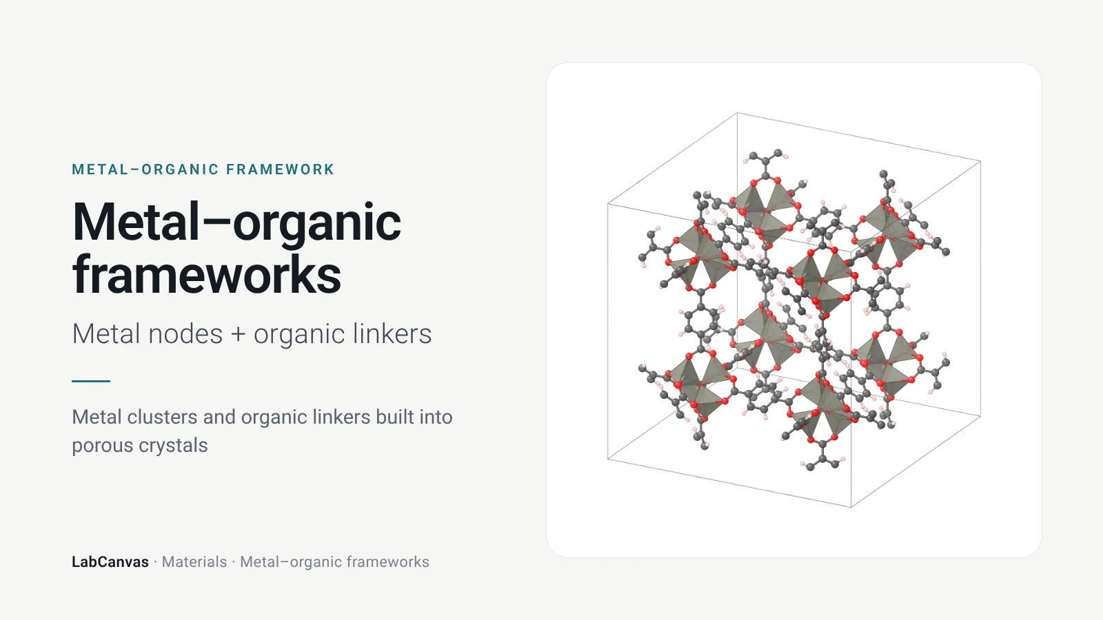
Metal–organic frameworks (MOFs) are crystalline, porous materials in which metal ions or metal–oxygen clusters are joined by organic linkers through coordination bonds into an open, periodic network. MOF-5, Zn₄O(terephthalate)₃, reported by Li, Eddaoudi, O’Keeffe and Yaghi in Nature in 1999, stays crystalline when its pores are emptied and reaches a BET surface area of about 3,800 m² g⁻¹ (Li et al. 1999; Kaye et al. 2007). Because the metal node and the linker can be chosen separately, MOFs with pores from a few ångströms to over 3 nm, open metal sites and high water stability have been made, and they are studied for gas storage, CO₂ capture, separations, catalysis and drug delivery.
Contents
Metal–organic frameworks at a glance
| Definition | Metal ions or clusters joined by organic linkers into crystalline, permanently porous frameworks (Li et al. 1999) |
|---|---|
| Landmark | MOF-5, Zn₄O(BDC)₃: crystalline after its pores are emptied and heated to 300 °C (Li et al. 1999) |
| Metal nodes (SBUs) | Zn₄O clusters (MOF-5), Cu₂ paddlewheels (HKUST-1), Zr₆O₄(OH)₄ clusters (UiO-66), single Zn²⁺ (ZIF-8), Cr₃O trimers (MIL-101) and metal–oxygen rods (MOF-74) |
| Linkers | Carboxylates such as terephthalate (BDC) and trimesate (BTC), imidazolates such as 2-methylimidazolate, and dobdc⁴⁻ (from the child pages) |
| Nets | pcu (MOF-5), tbo (HKUST-1), fcu (UiO-66), sod (ZIF-8) and the MTN zeotype (MIL-101) |
| Pore sizes | From 3.4 Å windows (ZIF-8) to mesoporous cages of about 30 and 34 Å (MIL-101) (Park et al. 2006; Férey et al. 2005) |
| Surface areas | BET about 3,800 m² g⁻¹ for MOF-5 handled air-free (Kaye et al. 2007); Langmuir about 5,900 m² g⁻¹ for MIL-101(Cr) (Férey et al. 2005) |
| Design | Isoreticular MOFs keep one net while the linker changes, so pore size and functionality can be designed (Eddaoudi et al. 2002) |
| Synthesis | Mostly solvothermal, from a metal salt and the linker acid in DMF or DEF at 85–220 °C; also at room temperature, in water, by ball milling and by extrusion (child pages) |
| Open metal sites | Removing solvent bound to the metal leaves sites that bind guests: Cu in HKUST-1, Mg in Mg-MOF-74 (Prestipino et al. 2006; Britt et al. 2009) |
| Stability | From MOF-5, which degrades in humid air (Kaye et al. 2007), to UiO-66, stable above 500 °C (Cavka et al. 2008), and MIL-101(Cr), stable in water at pH 0–12 (Ding et al. 2019) |
| Uses studied | Gas storage, CO₂ capture, separations and membranes, catalysis, drug delivery, sensors and electronics (child pages) |
MOF diagram

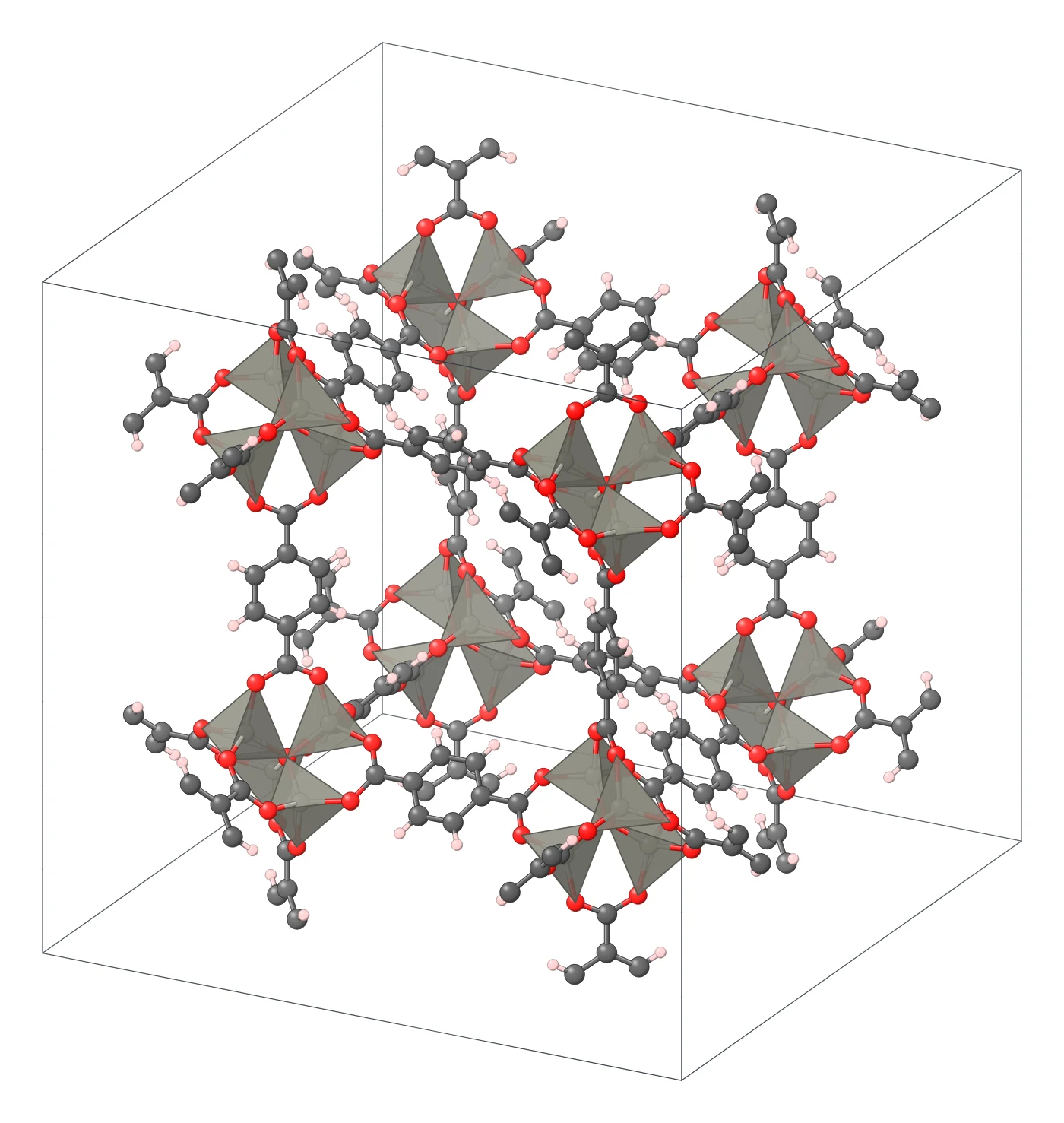
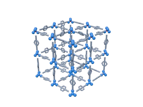
MOF crystal structure (high-resolution SVG)
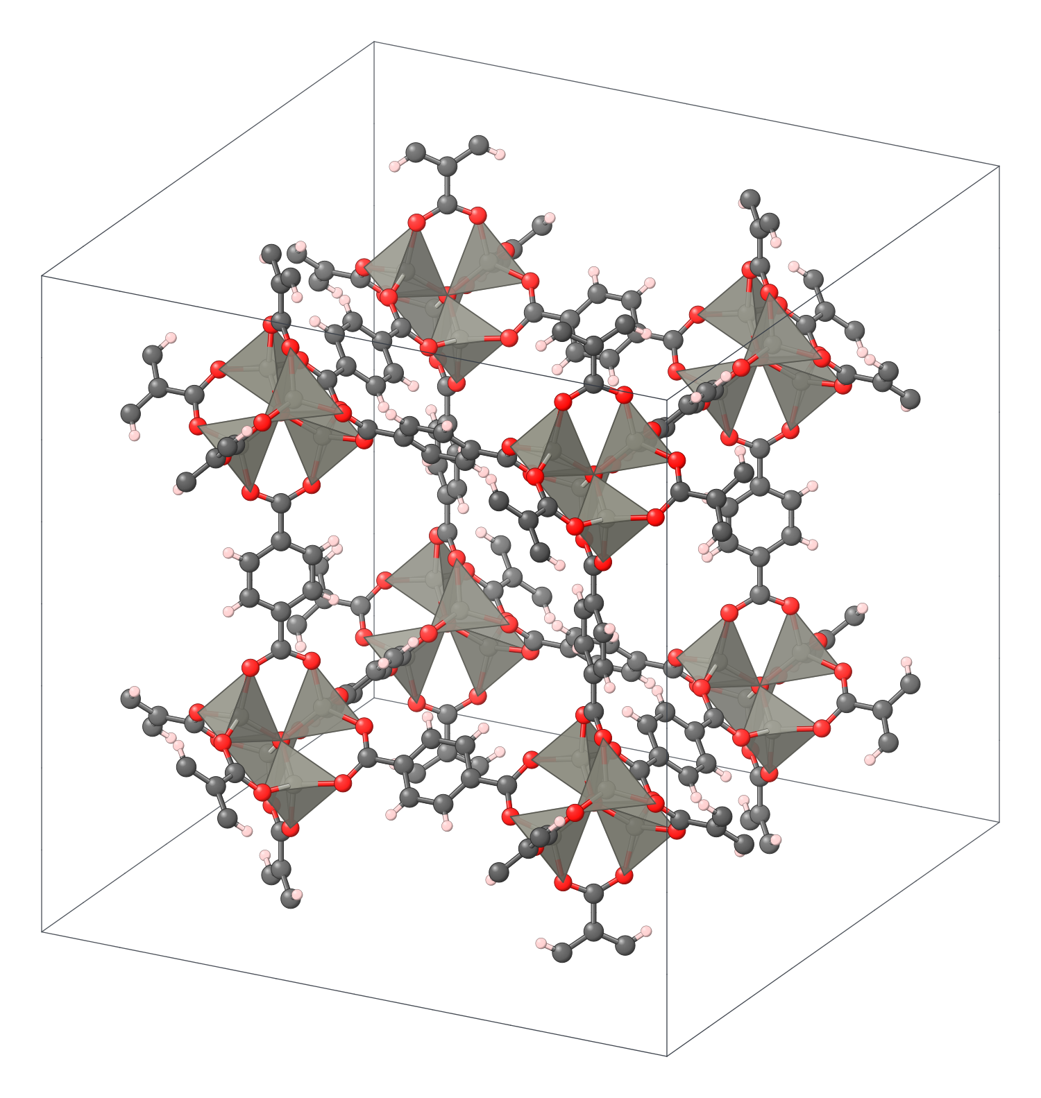
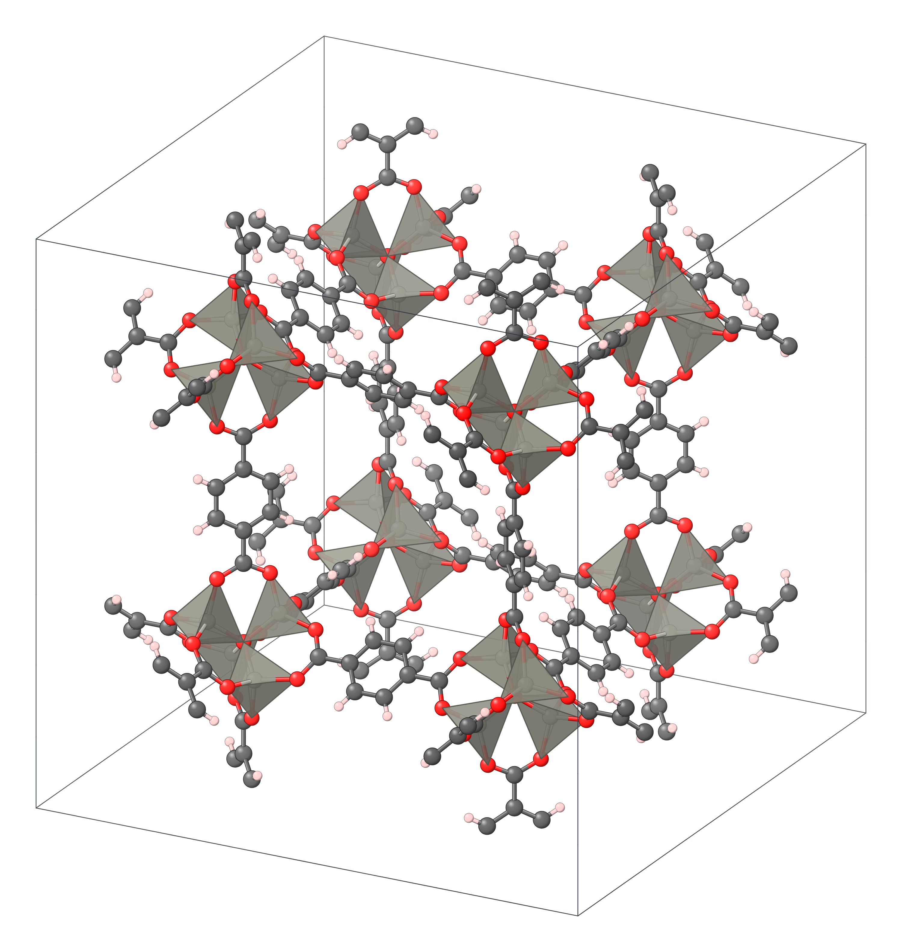
MOF in 3D (interactive)
Loading the 3D model…
More MOF figures

What is a metal–organic framework?
A metal–organic framework is built from two kinds of piece. The nodes are metal ions or small metal–oxygen clusters, often called secondary building units (SBUs); the linkers are rigid organic molecules, usually carboxylates or azolates, that bind a node at each end. Because each node accepts linkers in fixed directions and each linker has a fixed length, the pieces assemble into a regular, open network with pores of a defined size and shape.
Before 1999, most open coordination frameworks collapsed when their guest solvent was removed (Li et al. 1999). MOF-5, Zn₄O(BDC)₃, changed that: its octahedral Zn₄O(CO₂)₆ clusters, joined by terephthalate (BDC) into a cubic net, stay crystalline when the pores are emptied and heated to 300 °C (Li et al. 1999). Handled without air, MOF-5 reaches a BET surface area of about 3,800 m² g⁻¹ (Kaye et al. 2007).
The same year, Williams and co-workers reported the copper framework HKUST-1 (Chui et al. 1999), and the field grew quickly. The metal node and the linker can be chosen separately, so MOFs span a far wider range of compositions than zeolites, and unlike covalent organic frameworks they have metals in the backbone, which can act as catalytic or binding sites.
Nodes, linkers and nets: reticular design
A MOF can be reduced to a net: replace each node by a point and each linker by a line. The net depends on how many linkers each node takes and in which directions, and naming it gives a blueprint for making related frameworks. The six MOFs on this site show the main types of node:
- Zn₄O(CO₂)₆ clusters, six-connected octahedra, on the primitive cubic pcu net in MOF-5.
- Cu₂(CO₂)₄ paddlewheels, square four-connected units, joined by triangular trimesate on the tbo net in HKUST-1 (Kong et al. 2013).
- Zr₆O₄(OH)₄ clusters with twelve carboxylates, on the face-centred cubic fcu net in UiO-66 (Valenzano et al. 2011; Wu et al. 2013).
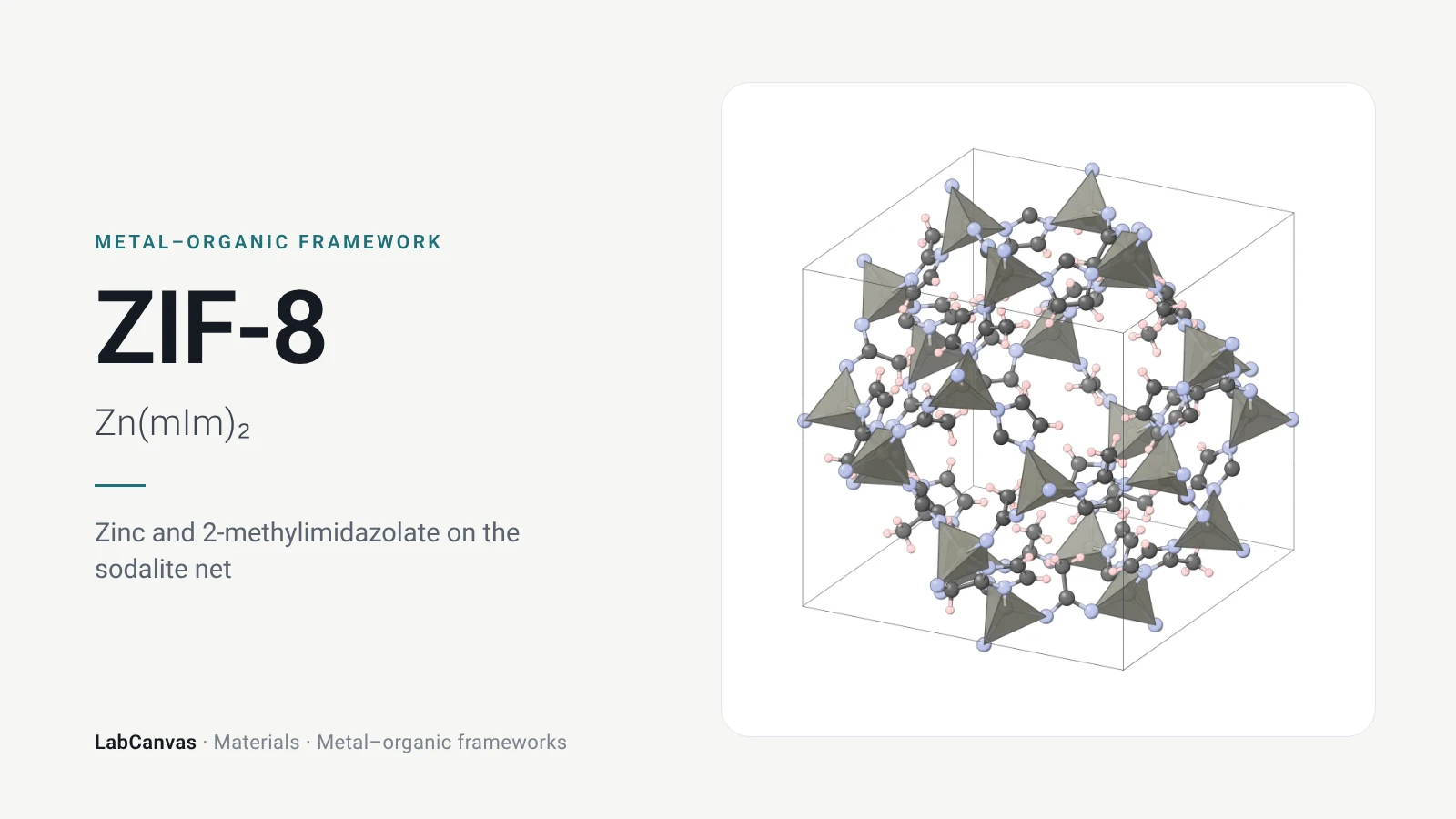
- Single tetrahedral Zn²⁺ ions joined by 2-methylimidazolate on the sodalite sod net in ZIF-8; the zinc takes the place of the tetrahedral Si of a zeolite and the imidazolate bridges two zinc ions as oxygen bridges two silicons, so zeolitic imidazolate frameworks take zeolite nets (Park et al. 2006).
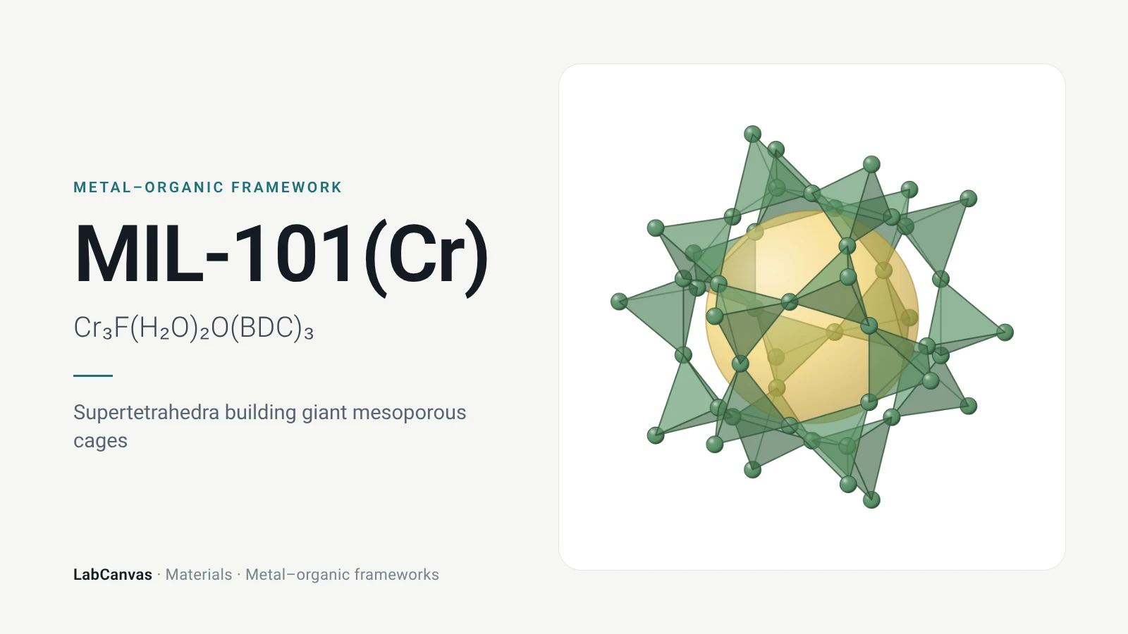
- Cr₃O trimers joined by terephthalate into supertetrahedra, which share corners on the MTN zeotype net in MIL-101(Cr) (Férey et al. 2005).
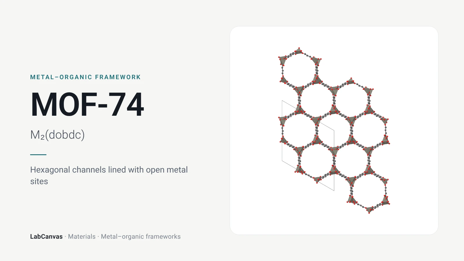
- Infinite metal–oxygen rods joined by dobdc⁴⁻ into a honeycomb of one-dimensional channels in MOF-74 (Rosi et al. 2005).
Keeping the net and changing the linker is called isoreticular design. In the IRMOF series, MOF-5 is IRMOF-1, and longer or functionalised linkers on the same pcu net gave frameworks with designed pore sizes and functional groups, tested for methane storage (Eddaoudi et al. 2002).
Pores, surface area and open metal sites
MOF pores range from windows narrower than many small molecules to mesoporous cages. ZIF-8 has cages 11.6 Å across joined by six-ring windows only 3.4 Å wide (Park et al. 2006), although the linkers swing so that the effective sieving aperture is 4.0–4.2 Å (Zhang et al. 2012). MOF-5 has alternating cavities about 12 and 15 Å across (Rowsell et al. 2005), HKUST-1 three kinds of pore about 12.6, 10.6 and 5.0 Å across (Wong-Ng et al. 2015), and MIL-101(Cr), with a giant cubic cell of about 702,000 ų, mesoporous cages of about 30 and 34 Å (Férey et al. 2005).
Surface area is measured from nitrogen adsorption at 77 K, usually with the Brunauer–Emmett–Teller (BET) equation fitted to the low-pressure part of the isotherm (see BET surface area):
where
In some MOFs, solvent molecules bound to the metal can be removed without collapsing the framework, leaving open metal sites that face the pores. In HKUST-1 the water on each copper is removed by heating under vacuum, and the bare Cu²⁺ sites then bind CO and H₂ at low temperature (Prestipino et al. 2006). MOF-74 has one such site per metal, which is why Mg-MOF-74 captures CO₂ so well (Britt et al. 2009).
How MOFs are made
Most MOFs are made by solvothermal synthesis: a metal salt and the linker acid are dissolved in a high-boiling solvent such as N,N-dimethylformamide (DMF) or N,N-diethylformamide (DEF), sealed and heated, and crystals grow as the acid is slowly deprotonated. Typical conditions on the pages here:
- MOF-5: zinc nitrate and terephthalic acid in DEF at about 85–105 °C (Eddaoudi et al. 2002).
- HKUST-1: copper(II) nitrate and trimesic acid in water/ethanol at 180 °C for 12 h (Chui et al. 1999).
- UiO-66: ZrCl₄ and terephthalic acid in DMF at 120 °C for 24 h (Cavka et al. 2008).
- Mg-MOF-74: magnesium nitrate and 2,5-dihydroxyterephthalic acid in DMF/ethanol/water at 125 °C (Caskey et al. 2008).
- MIL-101(Cr): chromium(III) nitrate, terephthalic acid, HF and water at 220 °C for 8 h (Férey et al. 2005).
Other routes avoid heat or solvent. ZIF-8 forms within minutes when methanol solutions of zinc nitrate and 2-methylimidazole are mixed at room temperature (Cravillon et al. 2009), and water can replace methanol (Pan et al. 2011). MOFs have been made by ball milling (Beldon et al. 2010; Užarević et al. 2016), by continuous extrusion with little or no solvent (Crawford et al. 2015), at the half-kilogram scale under reflux (Ragon et al. 2014), and as thin films from the vapour phase (Stassen et al. 2016). In zirconium MOFs, a modulator such as acetic or benzoic acid competes with the linker for the clusters and controls crystal size and defects (Schaate et al. 2011).
Activation comes last and matters as much as the synthesis: the solvent in the pores is exchanged for a more volatile one and removed under vacuum, often with heating. Air- and water-sensitive frameworks such as MOF-5 must be activated and kept dry (Kaye et al. 2007).
How MOFs are characterised
- X-ray diffraction (XRD). Single-crystal diffraction solves the structure; powder XRD compared with the pattern calculated from that structure confirms phase purity and shows whether the framework survives activation, heating or soaking. HKUST-1’s thermal stability to 240 °C was shown by thermogravimetry and high-temperature single-crystal diffraction (Chui et al. 1999).
- Gas sorption (BET). Nitrogen at 77 K gives surface area and pore volume; uptake of H₂, CH₄ or CO₂ tests a target use (Eddaoudi et al. 2002; Britt et al. 2009).
- Thermal analysis (TGA). Weight loss shows solvent removal and decomposition: above 500 °C for UiO-66 (Cavka et al. 2008), up to 550 °C for ZIF-8 (Park et al. 2006).
- Spectroscopy (FTIR, NMR). Shows the linker, bound guests and defects; infrared spectroscopy followed CO and H₂ binding at the open copper sites of HKUST-1 (Prestipino et al. 2006).
- Defects. Missing linkers change the properties: a typical UiO-66 sample lacks about 10% of its linkers, which raises its pore volume and changes its gas uptake (Wu et al. 2013), and modulators tune this (Shearer et al. 2016).
Stability in water, heat and acid
Stability varies more among MOFs than any other property, and it often decides whether a MOF is useful. A useful rule is that strong, inert metal–linker bonds give stable frameworks: the Cr³⁺–carboxylate bonds of MIL-101 make it far more resistant to water, acid and base than zinc carboxylates such as MOF-5 (as reviewed by Ding et al. 2019).
- MOF-5 degrades in humid air, so it is stored and handled dry (Kaye et al. 2007).
- HKUST-1 is stable to 240 °C (Chui et al. 1999), but water binds to its copper sites.
- ZIF-8 kept its crystallinity for 7 days in boiling water, methanol and benzene and for 24 h in 8 M sodium hydroxide at 100 °C (Park et al. 2006).
- UiO-66 decomposes only above 500 °C, resists most chemicals and stays crystalline under 10 tons/cm² of pressure (Cavka et al. 2008).
- MIL-101(Cr) is stable in water at pH 0–12 for 2 months (as reviewed by Ding et al. 2019).
What MOFs are used for
- Gas storage. MOFs were early candidates for methane and hydrogen storage (Eddaoudi et al. 2002; Kaye et al. 2007).
- CO₂ capture. Mg-MOF-74 has a dynamic CO₂ capacity of 8.9 wt% and releases the CO₂ at 80 °C (Britt et al. 2009); poly(ethylenimine)-loaded MIL-101(Cr) monoliths took up 1.05 mmol g⁻¹ of CO₂ from 400 ppm CO₂ at −20 °C (Wang et al. 2024).
- Separations and membranes. Thin ZIF-8 membranes separate propylene from propane (Kwon and Jeong 2013); Fe-MOF-74 separates olefins from paraffins (Bloch et al. 2012) and binds O₂ over N₂ (Bloch et al. 2011).
- Catalysis and protection. Modulated synthesis raises the catalytic activity of UiO-66 (Vermoortele et al. 2013), and UiO-66-NH₂ on fibres hydrolyses chemical warfare agent simulants (Lee et al. 2017).
- Drug delivery. MIL-100 and MIL-101 take up large amounts of drug molecules in their mesopores (Horcajada et al. 2006).
- Electronics and carbons. HKUST-1 films filled with TCNQ conduct electricity, with a tunable conductivity (Talin et al. 2014), vapour-deposited ZIFs are low-k dielectrics (Krishtab et al. 2019), and carbonised ZIF-8 gives porous carbons for supercapacitors (Chaikittisilp et al. 2012).
Six MOFs to know
- MOF-5 (IRMOF-1): Zn₄O clusters and terephthalate on the pcu net, the prototypical MOF (Li et al. 1999).
- HKUST-1 (Cu-BTC): copper paddlewheels and trimesate, 1 nm channels and open copper sites (Chui et al. 1999).
- UiO-66: twelve-connected Zr₆ clusters on the fcu net, the prototypical stable zirconium MOF (Cavka et al. 2008).
- ZIF-8: zinc and 2-methylimidazolate on the sodalite net, robust in boiling water and base (Park et al. 2006).
- MIL-101(Cr): supertetrahedra on a zeotype net with giant 30–34 Å cages (Férey et al. 2005).
- MOF-74 (CPO-27): metal–oxygen rods around hexagonal channels lined with open metal sites (Rosi et al. 2005; Britt et al. 2009).
How to draw a MOF
For a paper, slide or poster, show a MOF at three levels: the metal node and the linker, the net they form, and the crystal with a pore marked. The reticular design figure above shows these for MOF-5, HKUST-1 and UiO-66, with a library of nodes, linkers and nets, and the synthesis figure shows the common routes; both open as editable LabCanvas figures. The crystal structure drawing is a high-resolution SVG of MOF-5 from its crystal file, and the LabCanvas figure editor’s Library has crystal files for the other MOFs here, where you can switch between atoms and polyhedra and change the cells and view. The 3D model opens in the LabCanvas 3D Studio for a rendered image.
Six MOFs compared
| MOF | Formula | Metal node | Linker | Net | Pores | Surface area | Stability | First report |
|---|---|---|---|---|---|---|---|---|
| MOF-5 (IRMOF-1) | Zn₄O(BDC)₃ | Zn₄O cluster | Terephthalate | pcu | Cavities about 12 and 15 Å | Langmuir 2,900; BET about 3,800 m² g⁻¹ air-free | To 300 °C; degrades in humid air | Li et al., Nature 1999 |
| HKUST-1 | Cu₃(BTC)₂ | Cu₂ paddlewheel | Trimesate (BTC) | tbo | 1 nm channels; pores about 12.6, 10.6 and 5.0 Å | — | To 240 °C | Chui et al., Science 1999 |
| UiO-66 | Zr₆O₄(OH)₄(BDC)₆ | Zr₆ cluster | Terephthalate | fcu | Octahedral and tetrahedral cages | BET 1,000–1,600 m² g⁻¹ | Above 500 °C; most chemicals | Cavka et al., JACS 2008 |
| ZIF-8 | Zn(mIm)₂ | Single Zn²⁺ (tetrahedral) | 2-Methylimidazolate | sod | 11.6 Å cages, 3.4 Å windows | Langmuir 1,810; BET 1,630 m² g⁻¹ | To 550 °C; boiling water, hot NaOH | Park et al., PNAS 2006 |
| MIL-101(Cr) | Cr₃F(H₂O)₂O(BDC)₃ | Cr₃O trimer | Terephthalate | MTN (zeotype) | Cages about 30 and 34 Å | Langmuir about 5,900 m² g⁻¹ | Water at pH 0–12 for 2 months | Férey et al., Science 2005 |
| MOF-74 (CPO-27) | M₂(dobdc) | Helical M–O rod | dobdc⁴⁻ | Rod packing, 1D hexagonal channels | About 11–12 Å channels | BET 1,360 m² g⁻¹ (Fe₂(dobdc)) | Open metal sites bind water | Rosi et al., JACS 2005 |
Related materials
MOF-5
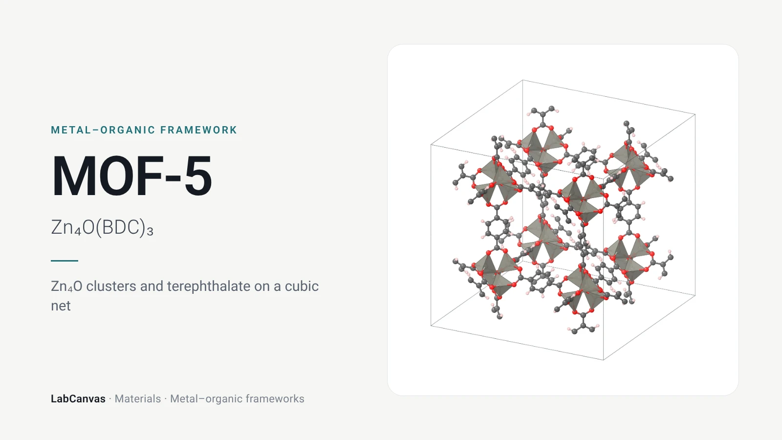
MOF-5, Zn₄O(BDC)₃: its cubic structure in 2D and interactive 3D, how it is made, surface area, stability and uses, with the original papers. Edit the figures free.
HKUST-1
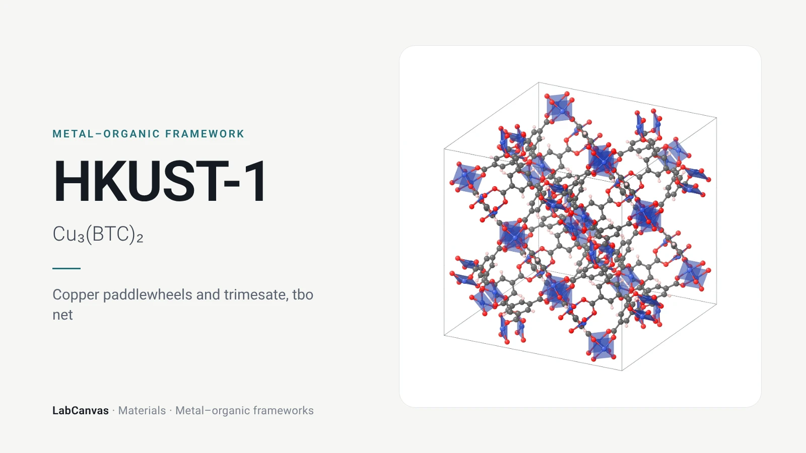
HKUST-1 (Cu-BTC), Cu₃(BTC)₂: its paddlewheel structure in 2D and 3D, how it is made, pore size, open copper sites and stability, with the original papers.
UiO-66
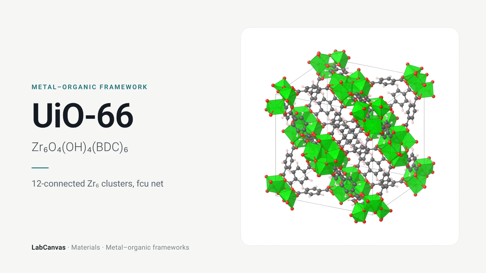
UiO-66, Zr₆O₄(OH)₄(BDC)₆: its fcu structure in 2D and 3D, how it is made, missing-linker defects, pore size, surface area and stability, with the papers.
ZIF-8
ZIF-8, Zn(mIm)₂: its sodalite structure in 2D and 3D, how it is made, pore size, surface area and stability, with the original papers. Edit the figures free.
MIL-101(Cr)
MIL-101(Cr), a chromium terephthalate MOF: its giant 30–34 Å cages, MTN structure, synthesis, surface area, water stability and uses, with the original papers.
MOF-74
MOF-74 (CPO-27), M₂(dobdc): its honeycomb channels and open metal sites, Mg-MOF-74 for CO₂ capture, Zn-MOF-74, synthesis and pore size, with the papers.
More on LabCanvas
- Reticular design: building units, linkers and nets: Editable figure template
- MOF synthesis: solvothermal, room temperature, modulated: Editable figure template
- More figure templates in this category: Ready-made, cited figures to edit
- Characterisation techniques explained: XRD, XPS, BET, SEM, TEM, NMR, FTIR, Raman and more
- Crystal structure figure software compared: VESTA, Mercury, CrystalMaker, Avogadro and LabCanvas
- XRD Scherrer crystallite size calculator: Free tool
- Molar mass calculator: Free tool
- Journal figure size guide: Column widths and resolutions for 38 journals
- 3D models gallery: Turn MOFs, COFs, perovskites and more in 3D
Frequently asked questions
What is a metal–organic framework (MOF)?
A crystalline, porous material made of metal ions or metal–oxygen clusters joined by organic linkers through coordination bonds. MOF-5, Zn₄O(terephthalate)₃, reported in Nature in 1999, was the first to show that such a framework can be emptied of solvent and stay crystalline and porous (Li et al. 1999).
What is a secondary building unit (SBU)?
The metal-containing node of a MOF, treated as one geometric unit: for example the octahedral Zn₄O(CO₂)₆ cluster of MOF-5, the square Cu₂(CO₂)₄ paddlewheel of HKUST-1 or the twelve-connected Zr₆O₄(OH)₄ cluster of UiO-66. Its shape and number of linkers decide the net the MOF can form.
What is the surface area of MOFs?
Often well above that of zeolites and activated carbons: MOF-5 reaches a BET surface area of about 3,800 m²/g when handled air-free (Kaye et al. 2007), and MIL-101(Cr) a Langmuir surface area of about 5,900 m²/g (Férey et al. 2005). UiO-66 gives 1,000–1,600 m²/g depending on defects (Wu et al. 2013).
How are MOFs made?
Most are made solvothermally, heating a metal salt and the linker acid in DMF or DEF in a sealed vessel. Some, like ZIF-8, form at room temperature in methanol or water; others are made by ball milling or extrusion. The pores are then activated by exchanging and removing the solvent (Eddaoudi et al. 2002; Cavka et al. 2008; Cravillon et al. 2009; Crawford et al. 2015).
Are MOFs stable in water?
Some are and some are not. MOF-5 degrades in humid air (Kaye et al. 2007), but ZIF-8 survives boiling water and hot sodium hydroxide (Park et al. 2006), UiO-66 resists most chemicals (Cavka et al. 2008), and MIL-101(Cr) is stable in water at pH 0–12 for 2 months (Ding et al. 2019).
What are open metal sites?
Metal atoms in a MOF left with a free coordination site after the solvent bound to them is removed. They face the pores and bind guests strongly: CO and H₂ at the copper sites of HKUST-1 (Prestipino et al. 2006) and CO₂ at the magnesium sites of Mg-MOF-74 (Britt et al. 2009).
What is the difference between a MOF and a ZIF?
A ZIF (zeolitic imidazolate framework) is a kind of MOF in which single tetrahedral metal ions such as Zn²⁺ are joined by imidazolate linkers. The metal takes the place of the tetrahedral Si of a zeolite and the imidazolate bridges two metals as oxygen bridges two silicons, so ZIFs take zeolite nets, like the sodalite net of ZIF-8 (Park et al. 2006).
What are MOFs used for?
Gas storage, CO₂ capture (Mg-MOF-74), separations and membranes (ZIF-8 for propylene/propane), catalysis (UiO-66), drug delivery (MIL-100, MIL-101), sensors and electronics, and as precursors to porous carbons (Britt et al. 2009; Kwon and Jeong 2013; Vermoortele et al. 2013; Horcajada et al. 2006; Chaikittisilp et al. 2012).
What is the difference between a MOF and a COF?
A MOF joins metal nodes with organic linkers through coordination bonds; a covalent organic framework (COF) has no metal in its backbone and joins organic building blocks with covalent bonds such as boronate ester or imine links. Both are crystalline and porous and both are designed from building blocks and nets.
References
- H. Li, M. Eddaoudi, M. O’Keeffe, O. M. Yaghi. Design and synthesis of an exceptionally stable and highly porous metal-organic framework. Nature 1999, 402, 276–279. doi:10.1038/46248
- S. S.-Y. Chui, S. M.-F. Lo, J. P. H. Charmant, A. G. Orpen, I. D. Williams. A chemically functionalizable nanoporous material [Cu₃(TMA)₂(H₂O)₃]ₙ. Science 1999, 283, 1148–1150. doi:10.1126/science.283.5405.1148
- M. Eddaoudi et al.. Systematic design of pore size and functionality in isoreticular MOFs and their application in methane storage. Science 2002, 295, 469–472. doi:10.1126/science.1067208
- J. L. C. Rowsell et al.. Gas adsorption sites in a large-pore metal-organic framework. Science 2005, 309, 1350–1354. doi:10.1126/science.1113247
- S. S. Kaye, A. Dailly, O. M. Yaghi, J. R. Long. Impact of preparation and handling on the hydrogen storage properties of Zn₄O(1,4-benzenedicarboxylate)₃ (MOF-5). J. Am. Chem. Soc. 2007, 129, 14176–14177. doi:10.1021/ja076877g
- K. S. Park, Z. Ni, A. P. Côté, J. Y. Choi, R. Huang, F. J. Uribe-Romo, H. K. Chae, M. O’Keeffe, O. M. Yaghi. Exceptional chemical and thermal stability of zeolitic imidazolate frameworks. Proc. Natl. Acad. Sci. USA 2006, 103, 10186–10191. doi:10.1073/pnas.0602439103
- J. H. Cavka, S. Jakobsen, U. Olsbye, N. Guillou, C. Lamberti, S. Bordiga, K. P. Lillerud. A new zirconium inorganic building brick forming metal organic frameworks with exceptional stability. J. Am. Chem. Soc. 2008, 130, 13850–13851. doi:10.1021/ja8057953
- G. Férey, C. Mellot-Draznieks, C. Serre, F. Millange, J. Dutour, S. Surblé, I. Margiolaki. A chromium terephthalate-based solid with unusually large pore volumes and surface area. Science 2005, 309, 2040–2042. doi:10.1126/science.1116275
- N. L. Rosi, J. Kim, M. Eddaoudi, B. Chen, M. O’Keeffe, O. M. Yaghi. Rod packings and metal–organic frameworks constructed from rod-shaped secondary building units. J. Am. Chem. Soc. 2005, 127, 1504–1518. doi:10.1021/ja045123o
- Kong et al.. Expanded organic building units for the construction of highly porous metal-organic frameworks. Chem. Eur. J. 2013, 19, 14886. doi:10.1002/chem.201302515
- L. Valenzano et al.. Disclosing the complex structure of UiO-66 metal organic framework: a synergic combination of experiment and theory. Chem. Mater. 2011, 23, 1700–1718. doi:10.1021/cm1022882
- H. Wu et al.. Unusual and highly tunable missing-linker defects in zirconium metal-organic framework UiO-66 and their important effects on gas adsorption. J. Am. Chem. Soc. 2013, 135, 10525–10532. doi:10.1021/ja404514r
- C. Prestipino et al.. Local structure of framework Cu(II) in HKUST-1 metallorganic framework: spectroscopic characterization upon activation and interaction with adsorbates. Chem. Mater. 2006, 18, 1337–1346. doi:10.1021/cm052191g
- W. Wong-Ng et al.. Reference diffraction patterns, microstructure, and pore-size distribution for the copper (II) benzene-1,3,5-tricarboxylate metal organic framework (Cu-BTC) compounds. Powder Diffr. 2015, 30, 2–13. doi:10.1017/S0885715614001195
- C. Zhang et al.. Unexpected molecular sieving properties of zeolitic imidazolate framework-8. J. Phys. Chem. Lett. 2012, 3, 2130–2134. doi:10.1021/jz300855a
- S. R. Caskey, A. G. Wong-Foy, A. J. Matzger. Dramatic tuning of carbon dioxide uptake via metal substitution in a coordination polymer with cylindrical pores. J. Am. Chem. Soc. 2008, 130, 10870–10871. doi:10.1021/ja8036096
- D. Britt, H. Furukawa, B. Wang, T. G. Glover, O. M. Yaghi. Highly efficient separation of carbon dioxide by a metal-organic framework replete with open metal sites. Proc. Natl. Acad. Sci. USA 2009, 106, 20637–20640. doi:10.1073/pnas.0909718106
- E. D. Bloch et al.. Selective binding of O₂ over N₂ in a redox-active metal–organic framework with open iron(II) coordination sites. J. Am. Chem. Soc. 2011, 133, 14814–14822. doi:10.1021/ja205976v
- E. D. Bloch et al.. Hydrocarbon separations in a metal–organic framework with open iron(II) coordination sites. Science 2012, 335, 1606–1610. doi:10.1126/science.1217544
- J. Cravillon, S. Münzer, S.-J. Lohmeier, A. Feldhoff, K. Huber, M. Wiebcke. Rapid room-temperature synthesis and characterization of nanocrystals of a prototypical zeolitic imidazolate framework. Chem. Mater. 2009, 21, 1410–1412. doi:10.1021/cm900166h
- Y. Pan et al.. Rapid synthesis of zeolitic imidazolate framework-8 (ZIF-8) nanocrystals in an aqueous system. Chem. Commun. 2011, 47, 2071. doi:10.1039/c0cc05002d
- P. J. Beldon et al.. Rapid room-temperature synthesis of zeolitic imidazolate frameworks by using mechanochemistry. Angew. Chem. Int. Ed. 2010, 49, 9640. doi:10.1002/anie.201005547
- K. Užarević et al.. Mechanochemical and solvent-free assembly of zirconium-based metal-organic frameworks. Chem. Commun. 2016, 52, 2133. doi:10.1039/c5cc08972g
- D. Crawford et al.. Synthesis by extrusion: continuous, large-scale preparation of MOFs using little or no solvent. Chem. Sci. 2015, 6, 1645. doi:10.1039/c4sc03217a
- F. Ragon et al.. In situ energy-dispersive X-ray diffraction for the synthesis optimization and scale-up of the porous zirconium terephthalate UiO-66. Inorg. Chem. 2014, 53, 2491. doi:10.1021/ic402514n
- I. Stassen et al.. Chemical vapour deposition of zeolitic imidazolate framework thin films. Nat. Mater. 2016, 15, 304. doi:10.1038/nmat4509
- A. Schaate et al.. Modulated synthesis of Zr-based metal-organic frameworks: from nano to single crystals. Chem. Eur. J. 2011, 17, 6643–6651. doi:10.1002/chem.201003211
- G. C. Shearer et al.. Defect engineering: tuning the porosity and composition of the metal–organic framework UiO-66 via modulated synthesis. Chem. Mater. 2016, 28, 3749–3761. doi:10.1021/acs.chemmater.6b00602
- M. Ding, X. Cai, H.-L. Jiang. Improving MOF stability: approaches and applications. Chem. Sci. 2019, 10, 10209–10230. doi:10.1039/c9sc03916c
- Y. Wang et al.. Cold temperature direct air CO₂ capture with amine-loaded metal–organic framework monoliths. ACS Appl. Mater. Interfaces 2024, 16, 1404–1415. doi:10.1021/acsami.3c13528
- H. T. Kwon, H.-K. Jeong. In situ synthesis of thin zeolitic-imidazolate framework ZIF-8 membranes exhibiting exceptionally high propylene/propane separation. J. Am. Chem. Soc. 2013, 135, 10763. doi:10.1021/ja403849c
- F. Vermoortele et al.. Synthesis modulation as a tool to increase the catalytic activity of metal-organic frameworks: the unique case of UiO-66(Zr). J. Am. Chem. Soc. 2013, 135, 11465. doi:10.1021/ja405078u
- D. T. Lee et al.. UiO-66-NH₂ metal-organic framework (MOF) nucleation on TiO₂, ZnO, and Al₂O₃ atomic layer deposition-treated polymer fibers: role of metal oxide on MOF growth and catalytic hydrolysis of chemical warfare agent simulants. ACS Appl. Mater. Interfaces 2017, 9, 44847. doi:10.1021/acsami.7b15397
- P. Horcajada, C. Serre, M. Vallet-Regí, M. Sebban, F. Taulelle, G. Férey. Metal–organic frameworks as efficient materials for drug delivery. Angew. Chem. Int. Ed. 2006, 45, 5974–5978. doi:10.1002/anie.200601878
- A. A. Talin et al.. Tunable electrical conductivity in metal-organic framework thin-film devices. Science 2014, 343, 66. doi:10.1126/science.1246738
- M. Krishtab et al.. Vapor-deposited zeolitic imidazolate frameworks as gap-filling ultra-low-k dielectrics. Nat. Commun. 2019, 10, 3729. doi:10.1038/s41467-019-11703-x
- W. Chaikittisilp et al.. Nanoporous carbons through direct carbonization of a zeolitic imidazolate framework for supercapacitor electrodes. Chem. Commun. 2012, 48, 7259. doi:10.1039/c2cc33433j
Draw Metal–organic frameworks for your paper or slides
LabCanvas is a browser workspace for scientific figures: framework clusters, linkers and nets, crystal structures in 2D and 3D, graphs and posters, all editable.
Edit the Metal–organic frameworks figure